PLC Motor and Drive Troubleshooting: A Layer-by-Layer Method
Diagnose a PLC-controlled motor by separating command logic, safety and permissives, starter or VFD interface, power, motor, feedback and mechanical load.
Review status: Editorially reviewed against cited regulator, drive-manufacturer, motor-manufacturer and measurement guidance; installed equipment ratings, test methods and safety procedures remain authoritative
Direct answer
Troubleshoot a PLC-controlled motor by finding the first point where commanded state and observed state disagree. Preserve the PLC status, drive or overload fault, safety state and process conditions before resetting anything. Then follow the energy and control chain in order: start request, PLC permissives, safety/STO status, PLC output or network command, relay/contactor or VFD input, motor power/current, motor and cable condition, mechanical load, and run/speed feedback. Test one boundary at a time and predict what each result will prove.
If the PLC output is on but the motor is stopped, the PLC is not automatically faulty. The break may be an open safety channel, missing interposing-relay voltage, failed contactor coil, tripped overload, VFD not-ready state, wrong command source, lost network control word, output-stage fault, motor/cable problem or seized load. Conversely, a running motor does not prove the sequence is healthy if the PLC never receives auxiliary, drive-running or speed feedback.
Motor and drive systems contain hazardous electrical energy, stored DC-bus charge and mechanical energy. A stop command, PLC output-off bit, HMI button or safety input is not an energy-isolating device. Use the site's documented energy-control procedure, qualified personnel, correctly rated instruments and manufacturer discharge/verification instructions. Never insulation-test through a connected VFD, and never bypass a safety function to “see if it runs.”
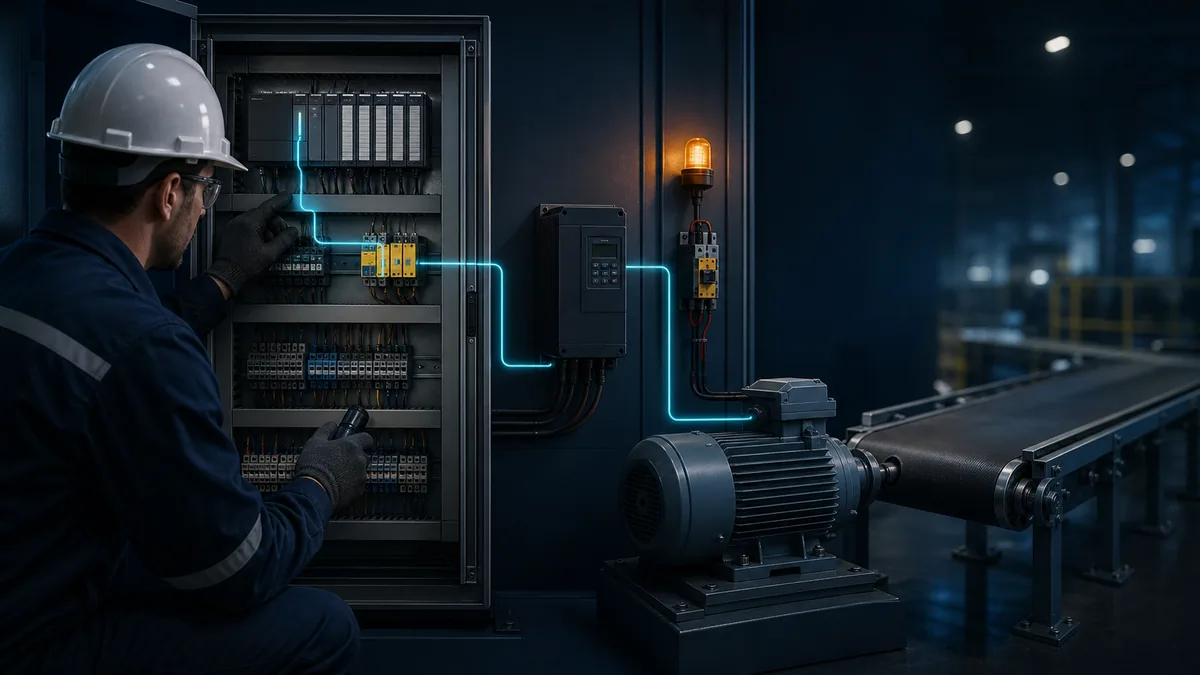
Define the motor-control boundaries
A motor “circuit” is several coupled systems. The PLC executes sequence logic. A safety system determines whether torque may be produced. A contactor starter or variable-frequency drive controls power. The motor converts electrical input to torque. A coupling, brake, gearbox, pump, fan or conveyor turns that torque into work. Feedback tells the PLC what actually happened.
The seven-boundary model
| Boundary | Command or energy entering | Expected evidence leaving | Common break |
|---|---|---|---|
| operator/sequence request | start mode, recipe or automatic step | latched/active run request | wrong mode, stale request, sequence not at step |
| PLC permissive logic | request plus process interlocks | run command bit | permissive false, timer, fault latch, hidden inhibit |
| safety system | closed guards, reset, valid channels | safety output/STO enabled state | guard open, channel discrepancy, safety fault, reset condition |
| PLC-to-starter/drive interface | output voltage or network control word | relay/contactor pickup or drive command accepted | output fault, open circuit, wrong source, lost connection |
| power controller | line power plus accepted command | motor current/torque-producing output | overload trip, drive fault, contactor pole, input/DC-link/output fault |
| motor and cable | three-phase electrical output | shaft torque and plausible current | phase/ground fault, winding, connection, insulation, thermal state |
| mechanical process and feedback | shaft torque | movement, flow/pressure and run/speed feedback | seized load, brake, coupling, sensor or feedback mapping |
This model prevents two common errors: treating a PLC bit as physical proof and treating a drive fault description as a root-cause verdict. Each indication is evidence for one boundary. Correlate it with evidence on both sides.
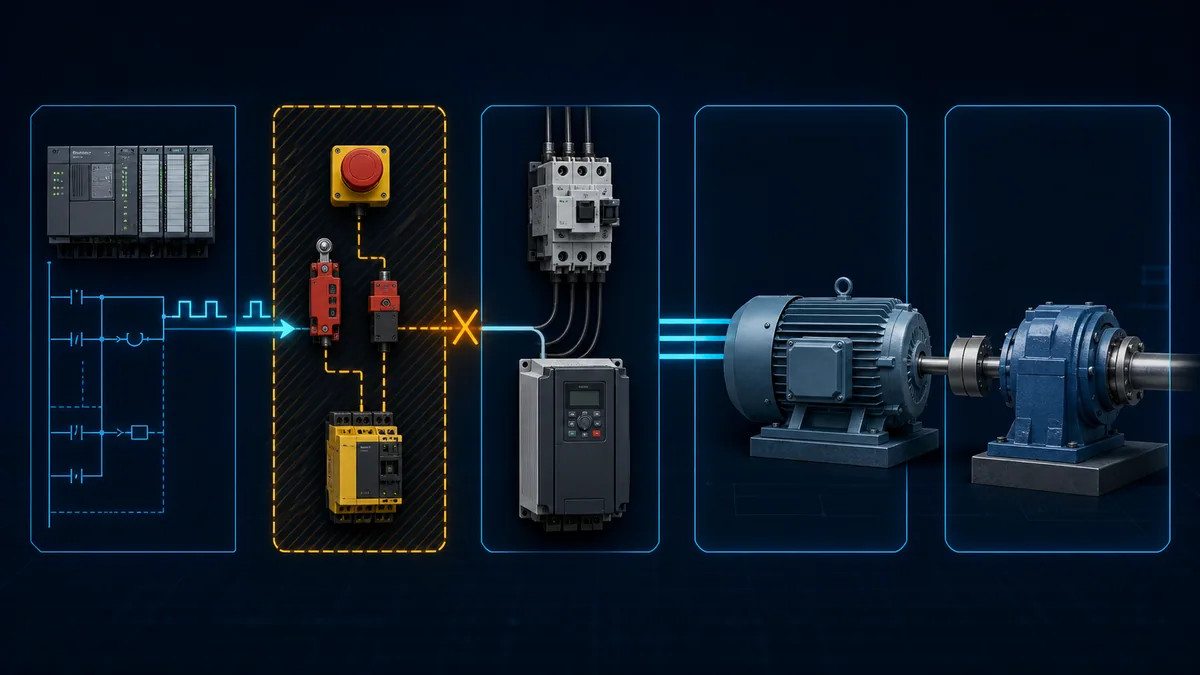
Preserve the fault before resetting
Resetting a drive or overload can erase the sequence of events, release a fault latch and allow an unexpected restart. First capture a consistent evidence packet. Use synchronized timestamps where possible; a PLC trend, drive clock and HMI alarm list that disagree by minutes can reverse the apparent cause-and-effect order.
Minimum evidence packet
| Evidence | Capture | Diagnostic value |
|---|---|---|
| symptom and time | stopped, slow, reverse, noisy, hot, tripped; first occurrence and duration | selects workflow and correlation window |
| operating context | mode, product, speed, load, recent maintenance, ambient state | exposes condition-dependent faults |
| PLC state | request, permissives, command, feedback, fault and sequence step | separates logic decision from physical response |
| safety state | safe-input channels, reset, output/STO status, diagnostic code | identifies valid safety inhibition without bypassing it |
| drive/starter state | ready, running, direction, reference, actual, warning, fault history, overload state | locates interface or power-controller rejection |
| electrical evidence | input conditions, output current, imbalance, DC-link/output measurements when authorized | distinguishes supply, controller and load paths |
| mechanical evidence | shaft/load state, brake, coupling, jam, pressure/flow, vibration and temperature | separates electrical current demand from process resistance |
| identity/version | PLC program revision, drive model/firmware, motor nameplate, parameter backup | makes manuals, limits and prior baselines applicable |
Save raw values rather than only colored HMI indicators. A green “motor available” object may combine several tags and delay states. The underlying ready, faulted, interlock, safety and communication bits are reproducible evidence.
Motor does not start
Use a left-to-right trace. The objective is not to “get the output on”; it is to identify the first missing prerequisite or response without defeating protection.
Ordered no-start workflow
- Confirm the requested mode and start condition are valid for the process.
- Observe the PLC run request, every permissive and the final command in the same scan window.
- Confirm the safety function reports its intended enabled state and no channel discrepancy.
- At the interface, prove the physical output voltage or network command and the destination's accepted-command status.
- For a starter, trace control voltage through relay, stop chain, overload contact and contactor coil; then check main-pole and auxiliary response.
- For a VFD, check ready/not-ready, command source, speed source, STO state, active fault/warning and actual command/reference.
- If power is delivered, compare motor currents and verify mechanical movement or load resistance using approved methods.
- Confirm feedback changes within the designed start timeout.
| Observation | Most useful interpretation | Next check |
|---|---|---|
| no PLC request | upstream mode, sequence or HMI issue | request owner, mode arbitration and sequence step |
| request on, final command off | permissive/interlock logic is intentionally blocking | first false condition and its physical source |
| PLC command on, physical output off | output module/channel, wiring or load-current problem | module status, terminal voltage and channel diagnostic |
| output on, contactor coil not energized | interposing relay, stop chain, overload contact or control wiring open | voltage across each boundary under command |
| VFD sees no command | source selection, network mapping or digital-input circuit | command source and accepted control word/input state |
| VFD commanded but not ready | safety/STO, active fault, enable or internal state | drive status/fault manual and safety diagnostics |
| controller produces output, motor has no current | open output path, contactor pole, cable or motor connection | isolated continuity/connection tests per procedure |
| motor current rises but shaft does not move | locked rotor, brake, seized motor or mechanical load | stop; isolate energy and inspect mechanical system |
Motor starts and then trips
The time from command to trip is evidence. An immediate high-current or ground fault suggests a different branch from an overload after several minutes, an overvoltage during deceleration or an intermittent network loss. Record elapsed time, command/reference, actual speed, current and process load.
Trip-timing matrix
| Timing or event | Candidate families | Discriminating evidence |
|---|---|---|
| immediately on start command | short/ground fault, wrong motor connection, seized load, very short ramp, excessive boost, contactor/output fault | exact trip code, current rise, isolated motor/cable test, shaft/load state |
| during acceleration | current limit, overload, insufficient torque, brake not releasing, load too high, acceleration too short | current/torque trend, ramp, brake feedback and mechanical load |
| at steady load | sustained overload, cooling loss, phase/current imbalance, process restriction | current by phase, load baseline, temperature, fan/airflow and process values |
| during deceleration | regenerative DC-bus overvoltage, braking configuration or overhauling load | DC-bus trend, deceleration ramp, brake/chopper/resistor status |
| only at low speed | inadequate cooling, torque/boost issue, mechanical resonance or minimum-speed process problem | motor thermal method, current/torque, speed and vibration trend |
| after a repeatable time | thermal model, timer/interlock, lubrication or process accumulation | fault history, PLC timer, motor/drive thermal state and load trend |
| random under vibration/heat | loose connection, encoder/feedback, fan, contamination, network or insulation deterioration | event trend plus environmental correlation |
Rockwell's PowerFlex 525 product information demonstrates why the raw code and context matter: separate faults exist for power loss, over/undervoltage, stall, motor overload, heatsink temperature, hardware/software overcurrent, ground fault, phase loss, communication loss and encoder loss. Other manufacturers use different code numbers and thresholds; use the exact installed manual.
Direct-on-line starter path
A direct-on-line or reversing starter has a low-voltage control path and a three-phase power path. The PLC usually commands an interposing relay or contactor coil. An overload auxiliary contact and contactor auxiliary feedback return state. The main poles switch motor power. Proving only one path is insufficient.
Trace control and power separately
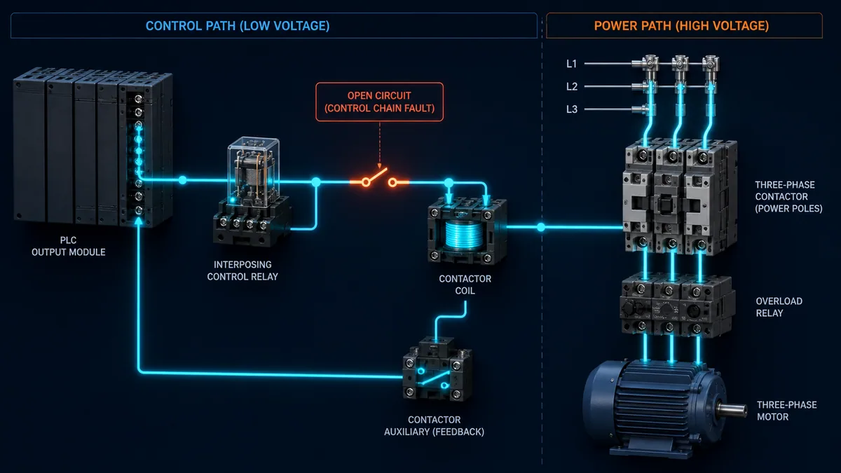
| Test point | Commanded-off expectation | Commanded-on expectation | Fault indicated by mismatch |
|---|---|---|---|
| PLC logic output tag | false | true after permissives | sequence/logic owner if false unexpectedly |
| output terminal to control common | de-energized per design | rated control signal within documented tolerance | channel/module/supply/wiring issue |
| interposing relay contact | open | closed with correct contact voltage drop | relay coil/contact or socket issue |
| overload NC auxiliary | closed if healthy | remains closed during normal start | overload trip, wrong contact or wiring |
| contactor coil | de-energized | rated coil supply present | upstream control-path break or wrong coil rating |
| contactor main poles | open | closed with balanced supply to motor | worn/failed pole, mechanical contactor fault |
| auxiliary feedback | off | on within pickup time | auxiliary contact/mapping or contactor response |
| motor current | zero | plausible and balanced for state/load | power path, motor or load problem |
Measure a coil across its terminals, not merely from one side to an assumed ground. The correct expected voltage is the coil nameplate/control-circuit value and manufacturer tolerance. A high-impedance meter can display coupled or leakage voltage that collapses under load; interpret it using the approved circuit diagram and suitable test method.
Live mini-lab
Try it: press START, then STOP
A stop-dominant seal-in rung: START latches the motor output through its own contact, and STOP breaks the circuit.
Watch the output lamp: it stays on after START until you press STOP.
Free to start · runs in your browserOpens plcsimulationsoftware.com — same team
VFD-controlled motor path
A VFD introduces command-source selection, speed-reference selection, enable/STO inputs, rectifier and DC link, inverter output, motor-model parameters, acceleration/deceleration profiles, current/torque limits, network state and internal fault history. Divide the system into input, conversion/control and output/load zones.
Verify state before energized measurements
Start with the keypad/software diagnostics: ready, active command source, accepted run/direction, reference source and value, actual frequency/speed, output current, DC bus, active limit, warnings, fault queue and network status. These non-invasive values often identify the boundary before a qualified person performs energized measurements.
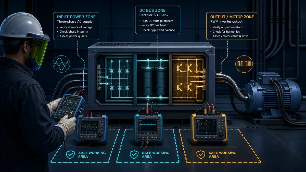
| VFD zone | Non-invasive evidence first | Authorized measurement concept | Frequent error |
|---|---|---|---|
| input supply | line/phase loss history, input/DC-bus diagnostic, fault timestamp | phase-to-phase supply and power quality with appropriately rated equipment | blaming the motor for upstream dips or imbalance |
| DC link | displayed bus and over/undervoltage history | only at designated terminals using discharge and live-work procedures | assuming the display/off LED proves absence of voltage |
| control | ready, source, command, reference, limit and STO status | digital/analog/network signal at defined reference | command exists in PLC but drive listens to another source |
| inverter output | output frequency/current and fault diagnostics | PWM-capable meter or motor-drive analyzer as manufacturer requires | interpreting PWM with an unsuitable general-purpose meter |
| motor cable | ground/phase fault and reflected-wave context | isolated cable/motor tests after disconnecting drive | applying insulation-test voltage to drive electronics |
| motor/load | current, torque estimate, speed feedback and thermal model | current, vibration, temperature and mechanical checks | clearing overload without finding excess load/cooling cause |
Fluke's output-measurement guidance explicitly separates DC-bus, output voltage/current/frequency, unbalance, volts-per-hertz and output reflections. It also calls for instruments suited to PWM drive output. An ordinary meter result that looks unlike line-frequency sine-wave voltage does not by itself prove a failed inverter.
PLC command, permissive and feedback logic
Online monitoring must distinguish desired state, issued command and confirmed state. A well-instrumented motor object exposes the reason it is inhibited, the owner of the command, transition timing and feedback disagreement. Forcing a bit can make the display appear correct while the physical chain remains unsafe or invalid.
Logic evidence checklist
| PLC signal | Diagnostic question | Better implementation evidence |
|---|---|---|
| start request | which source requested run and in what mode | source enum plus timestamp, not one merged Boolean |
| permissive summary | which exact permissive is false | bitfield/array and first-out capture |
| run command | did logic issue forward/reverse/run | command state with sequence step and owner |
| output/network health | could the controller deliver that command | module channel diagnostic or connection status |
| run feedback | did contactor/drive acknowledge running | raw feedback plus debounced state and transition time |
| speed feedback | did motion reach the commanded band | reference, actual, tolerance and timeout |
| trip/fault | which device originated the stop | latched first-out source plus raw device code |
| restart state | can the motor restart automatically after recovery | documented restart mode and operator notification |
If a command chatters, examine the rung and input transitions at a sampling rate that can see the event. HMI history polling may miss a one-scan permissive drop. Use a PLC trace, sequence-of-events function or high-speed trend appropriate to the controller, while keeping trace load and retention controlled.
Safety and STO boundary
Safe Torque Off normally prevents the drive from producing motor torque; it is not a general energy-isolation method, and it does not necessarily remove hazardous voltage from the drive or motor terminals. The installed safety design, risk assessment, drive safety manual and applicable standards define its role.
Diagnose without bypassing protection
Read both safety input channels, reset/acknowledge conditions, discrepancy time, safety-controller diagnostics, safety output state and drive STO status. Compare the raw channels with the safety function's validated truth table. A guard can be physically closed while one contact or channel remains open. Do not bridge STO terminals, force safety outputs or change a safety signature as a troubleshooting shortcut.
| Safety observation | Candidate cause | Approved evidence path |
|---|---|---|
| both channels open | open guard/E-stop, missing supply or series-circuit break | device state and channel-by-channel wiring diagram |
| channels disagree | contact timing, broken conductor, misalignment or channel fault | safety diagnostic code and physical inspection under procedure |
| inputs valid but reset denied | reset edge, monitored reset, other zone or latched fault | function block status and validated reset sequence |
| safety output valid, drive STO active | downstream safety wiring, drive terminals/configuration or status mapping | safety output terminals and drive safety diagnostics |
| motor stopped but hazardous power present | expected STO behavior may be misunderstood | do not touch; isolate energy using formal procedure |
OSHA identifies push buttons, selector switches and control-circuit devices as not being energy-isolating devices for hazardous-energy control. That principle is crucial when a PLC screen shows “off.”
Supply, DC bus and drive-output faults
Begin drive electrical diagnosis at the input, then move through the DC link to the output only when evidence and authorization require it. Fluke's input-side guidance recommends checking supply voltage, current and frequency because upstream capacity, imbalance, dips or distortion can affect drive operation and life.
Symptom-to-zone map
| Symptom/fault family | Probable zone | Evidence before replacement |
|---|---|---|
| undervoltage/power loss | upstream supply, fuse/contactor, connection or severe load dip | timestamped input and bus trend, input protection and other-load correlation |
| overvoltage at deceleration | regenerated load energy, decel ramp or braking system | bus trend, load direction/inertia, brake chopper/resistor state and configured ramp |
| input phase loss/imbalance | feeder, fuse, contactor pole or connection | phase-to-phase values and current under comparable load |
| output phase loss | output connection, cable, motor winding or drive output | drive code, current pattern and isolated motor/cable evidence |
| ground fault | motor cable, motor insulation, junction or output stage | disconnected cable/motor tests per vendor method; never megger through drive |
| overcurrent/stall | jam/brake, acceleration, motor data, cable/motor fault or tuning | current/torque trend, mechanical state, ramp and motor parameter verification |
| drive/heatsink overtemperature | ambient, airflow, contamination, fan or load | temperature history, fan and enclosure/filter condition, output current |
| communication loss | network path, adapter, PLC connection or timeout/action configuration | connection diagnostics, switch/cable counters and drive comm-loss history |
A fault-clear that temporarily restores operation is not corrective evidence. If the same condition returns, preserve its timestamp and trend, compare to operating context and correct the cause before authorizing normal service.
Motor, cable and insulation checks
Only test after applying the equipment's isolation procedure, proving absence of hazardous energy and disconnecting sensitive electronics as required. Record motor nameplate, connection, cable length/type, drive carrier/output context, ambient temperature and prior readings. A resistance value without test voltage, temperature, duration and connection is poor evidence.
De-energized motor evidence
| Check | What it can reveal | Important limitation |
|---|---|---|
| visual/connection inspection | loose lugs, heat damage, contamination, wrong star/delta link, damaged cable | torque and configuration follow manufacturer procedure |
| phase-to-phase winding resistance | gross imbalance, open joint or connection problem | very low values require appropriate instrument and lead compensation |
| insulation resistance to frame/PE | insulation contamination or deterioration | disconnect drive/sensors; test voltage, duration, temperature and limits are motor-specific |
| phase-to-phase insulation test where specified | winding/cable insulation issues | do not invent procedure; coordinate with motor manufacturer for sensitive designs |
| cable-only insulation/continuity | separates feeder cable from motor winding | disconnect both ends and protect other connected devices |
| rotation/mechanical feel under isolation | seized bearing/load, brake or coupling issue | stored mechanical energy and load movement still require control |
| temperature-corrected trend | deterioration relative to baseline | one generic pass number cannot replace product/site criteria |
Siemens motor instructions warn that high-voltage insulation tests can damage insulation when the procedure is not appropriate, require compliant test equipment and define motor-specific limits and connections. Apply those instructions only to the named motor family. They demonstrate why a value copied from a different motor manual is not a universal acceptance criterion.
ABB guidance for motors on PWM drives adds another system concern: the converter output can impose insulation stress, while cable arrangement, grounding, filtering and motor design affect reflected voltage and bearing-current risk. A replacement motor of the same power rating is not automatically equivalent for inverter duty, cable length and switching conditions.
Separate the motor from the mechanical load
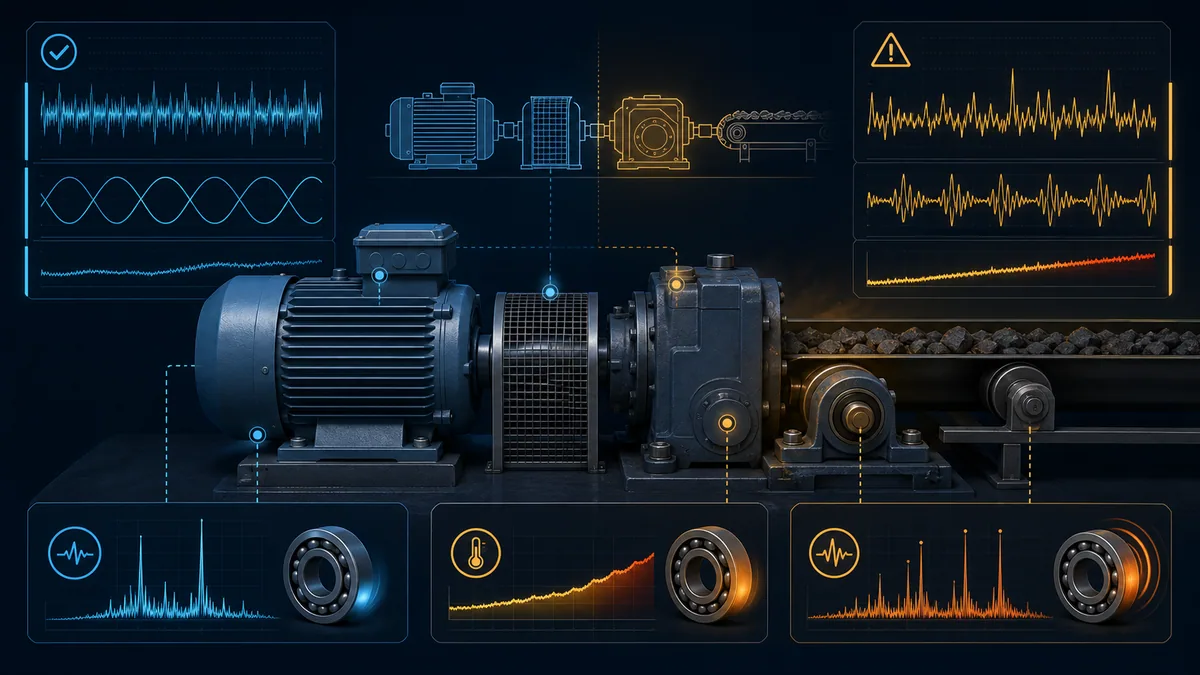
Electrical current reflects the torque demanded by the mechanical system. A healthy motor can trip because a conveyor is jammed, a pump valve/process condition raises load, a brake remains applied, a bearing fails or a gearbox binds. Conversely, a damaged motor can produce abnormal current with an unloaded shaft.
Electrical-versus-mechanical evidence
| Evidence pattern | More consistent with | Confirmation approach |
|---|---|---|
| balanced high current with high process load | genuine mechanical/process overload | compare pressure/flow/tension and mechanical inspection to baseline |
| high current with zero speed | locked rotor, brake or severe jam | stop immediately; isolate and inspect before another start |
| one phase current abnormal | supply/output connection, winding or measurement issue | phase comparison at defined points and isolated tests |
| normal current but low process output | coupling slip/break, pump/process issue or feedback error | shaft/load speed and process evidence |
| vibration at particular speed | resonance, alignment, bearing or mechanical looseness | controlled speed/vibration analysis by qualified personnel |
| rising bearing temperature over time | lubrication, alignment, load or bearing damage | temperature/vibration trend and mechanical inspection |
| drive current estimate disagrees with external suitable instrument | scaling, sensor, PWM measurement or drive issue | verify instrument method and drive diagnostics |
Decoupling a load can be useful only if the manufacturer and site authorize it and the motor, key, coupling, brake and machine are secured for an uncoupled test. Removing a guard and running exposed rotating parts is not a troubleshooting shortcut.
Speed, direction and feedback errors
A motor that runs at the wrong speed may have the correct run command but the wrong reference owner, scale, limit or feedback interpretation. Direction errors can come from command logic, phase sequence in a starter system, drive direction configuration or feedback polarity. Establish the intended direction and safe test condition before changing leads or parameters.
Command-versus-actual matrix
| Command evidence | Actual evidence | Likely branch |
|---|---|---|
| zero reference, motor turns | minimum speed, jog, local mode, stale network command or mechanical back-drive | source/mode, minimum limits and local controls |
| nonzero reference, actual remains zero | not enabled, STO, brake, current limit, load or feedback failure | ready/status/limit plus shaft observation |
| reference correct, output frequency capped | max-frequency limit, current/torque limit or process override | active limit and parameter ownership |
| output frequency plausible, shaft speed wrong | pole/nameplate data, slip/load, belt/gear ratio or encoder scaling | motor data and independent speed measurement |
| shaft direction wrong | reverse command, phase order or configured polarity | command bits and approved rotation test |
| motor runs, PLC reports stopped | auxiliary/drive status mapping, input wiring or debounce/timing | raw feedback at device, input and PLC tag |
| oscillating speed | unstable control loop, noisy reference, load variation or encoder issue | reference/actual/torque trend at sufficient sample rate |
When changing two motor leads for direction on a VFD installation, follow the drive/motor procedure with energy isolated; do not switch output contactors while the drive is producing output unless the approved design explicitly supports that operation.
Intermittent motor and drive faults
Intermittent events need synchronized history, not repeated manual snapshots. Trend command source, run request, critical permissives, safety status, drive ready/run/fault, raw fault code, reference, actual speed, output current/torque, DC bus if exposed diagnostically, device temperature, network status and process load.
Triggered capture plan
| Trigger | Pre-event window | Post-event window | Supporting environmental signal |
|---|---|---|---|
| first drive fault bit | long enough to see command/load change | through reset decision | cabinet temperature, line event, adjacent large load |
| feedback lost while command remains | several start/steady-state cycles | through timeout and stop | vibration, connector movement, network counters |
| current exceeds baseline | ramp and prior process state | through trip or recovery | pressure, material load, brake state |
| safety channel discrepancy | guard/stop transitions | through reset attempt | door position, vibration, channel raw inputs |
| network connection loss | connection health before event | reconnection and command restoration | switch port errors, topology change, power dip |
Use the broader intermittent PLC fault troubleshooting guide for vibration, moisture, temperature, EMI and evidence-window methods. The motor/drive page remains focused on the command-to-torque chain.
Controlled restoration and acceptance
After a cause is corrected, restoration is a test with predicted results—not a reset followed by immediate production. Review the change, confirm guards and connections, remove test equipment and temporary configurations, restore parameters from controlled records, notify affected personnel and follow the site's restart procedure.
Acceptance evidence
| Acceptance item | Pass evidence | Failure response |
|---|---|---|
| command/permissive behavior | correct owner and every interlock proven in intended state | return to logic/sensor diagnosis |
| safety function | validated response and reset behavior per safety procedure | stop; safety-qualified review |
| start transition | ready, command, pickup/run feedback within designed time | preserve trace and locate delayed boundary |
| current/load | plausible, balanced and within equipment/application limits | investigate motor/load/supply before release |
| speed/direction | correct across approved operating points | verify source, scaling, parameters and mechanics |
| stop/deceleration | intended stop category with no bus/overload fault | review load energy, ramp and braking design |
| fault handling | correct first-out, alarm, reset authorization and restart policy | fix diagnostic/control design before release |
| sustained run | temperature, vibration, process and network remain stable for defined window | extend monitoring or reopen root-cause analysis |
Record what changed, why it corrected the predicted boundary, the before/after evidence and any remaining risk. “Replaced VFD and it runs” is not a strong root-cause record if a loose input connection or seized load can damage the replacement.
Simulator lab for diagnostic practice
A simulator can inject command, permissive, feedback, overload, network and drive-state faults without bypassing a real safety function or experimenting with production outputs. The learning objective is to choose a discriminating observation, predict its result and stop when evidence changes the fault boundary.
Six fault cases to rehearse
| Case | Injected condition | Correct first evidence | Common wrong conclusion |
|---|---|---|---|
| PLC output never energizes | process permissive false | individual permissive and sequence step | replace output module |
| output energizes, starter stays open | overload auxiliary open | control-path voltage across documented contacts | PLC logic is wrong |
| VFD ready but ignores run | local/keypad command source selected | active command source and accepted run bit | network cable failed |
| motor accelerates then trips | mechanical load plus short acceleration | current/torque versus ramp and load | drive is undersized |
| motor runs, PLC times out | auxiliary feedback input open | physical running state versus raw PLC input | motor failed to start |
| intermittent comm loss | switch/connection event | timestamped network and drive fault history | increase every timeout |
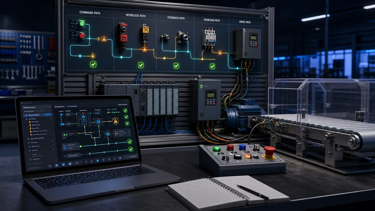
Practise the VFD command, reference, feedback and fault chain in the VFD simulator. The lab continues the diagnostic task; it does not reproduce every manufacturer's protection model, output waveform or safety certification.
Diagnostic answer map for search and AI-assisted troubleshooting
| User or AI query | Concise answer | Essential condition |
|---|---|---|
| PLC output is on but the motor is not running | Trace the physical interface, safety/STO, starter or drive ready state, power output, motor and load. | An online PLC bit is not proof of terminal voltage or motor power. |
| Motor starts then trips after a few seconds | Save the exact trip and trend current, ramp, brake and mechanical load from before the start. | Do not reset until fault history and operating context are captured. |
| VFD says run but motor does not turn | Check ready/STO, active source, accepted reference, output frequency/current, motor path and mechanical brake/load. | Use the exact drive status model and safe measurement procedure. |
| Contactor coil has voltage but does not pull in | Verify voltage across the coil matches its rating under load, then inspect coil/mechanism under isolation. | A high-impedance ghost reading can mislead; do not hold the contactor manually. |
| VFD overvoltage fault during stopping | Regenerated load energy may raise the DC bus; examine decel ramp and braking design. | Input overvoltage and device-specific faults must also be excluded. |
| VFD overcurrent fault during acceleration | Check jam/brake/load, acceleration, motor data, boost/tuning and cable/motor fault evidence. | A code identifies protection action, not one guaranteed cause. |
| Motor current high on all phases | The motor may be genuinely overloaded or under-volted, incorrectly connected or driven with bad parameters. | Compare process/mechanical load and supply to nameplate/application limits. |
| Motor runs but PLC reports stopped | Trace auxiliary/drive run feedback from device contact/status through wiring/network and PLC mapping. | Confirm the motor is physically running before altering feedback logic. |
| Can I megger a motor connected to a VFD? | Normally disconnect the motor cable from drive electronics and follow both manuals before insulation testing. | Never apply insulation-test voltage through a connected VFD. |
| Can STO be used as lockout | STO prevents torque when correctly functioning but is not automatically an energy-isolating device. | Follow the site's energy-control procedure and drive safety manual. |
Frequently asked questions
What should I check first when a PLC-controlled motor will not start?
Capture the fault state, then compare the start request, individual permissives, safety/STO state, final PLC command and physical starter/drive response. The first mismatch defines the next test. Do not begin by resetting the drive or forcing the output.
Why is the PLC output on but the contactor is not energized?
The output tag may not equal terminal voltage, or the downstream control chain may be open. Check module/channel diagnostics, voltage at the output, interposing relay, stop circuit, overload auxiliary contact, coil supply and return using the approved schematic and test method.
Why does a motor start and then trip on overload?
Possible causes include excessive mechanical/process load, brake not releasing, acceleration too short, incorrect motor parameters, low-speed cooling limits, phase/current imbalance or motor/cable damage. Save current, timing, load and the exact protection state before reset.
How do I tell whether the VFD, motor or load is faulty?
Separate input supply, drive state/output, motor/cable and mechanical load. Compare command, ready, output frequency/current, shaft response, current balance, process load, vibration and temperature. Use isolated tests only under the manufacturer and site procedure.
Can a normal multimeter measure VFD output voltage accurately?
Not necessarily. PWM output contains fast switching components and requires a meter or motor-drive analyzer with the appropriate VFD/PWM method, rating and bandwidth. Follow the drive and instrument manufacturers' connection and interpretation guidance.
Should I reset a VFD as soon as it faults?
No. First preserve the current fault, history, timestamp, command/reference, current, DC-bus diagnostic, temperature, network state and process load. A reset can erase first-out evidence and may permit an unexpected restart.
How do I test motor insulation on a VFD system?
Apply the formal isolation procedure, verify absence of hazardous energy, disconnect the motor/cable from sensitive drive electronics as required, and use the motor and drive manufacturers' test voltage, connection, time, temperature correction and acceptance criteria.
Why does the motor run locally from the VFD but not from the PLC?
Local operation proves much of the drive, motor and load path, but not remote command. Check remote/local mode, active command and reference sources, network ownership, digital inputs, control word, safety state and PLC-to-drive mapping.
Is Safe Torque Off the same as electrical isolation?
No. STO is a safety function intended to prevent torque when correctly applied, but hazardous voltage and stored DC-bus energy may remain. Use the equipment's documented energy-isolation and verification procedure for servicing.
What proves a motor troubleshooting repair is complete?
A controlled restart should prove command ownership, permissives, safety response, start timing, current/load, speed/direction, feedback, stop behavior and fault handling over a defined operating window. Record the corrected boundary and before/after evidence.
Sources, review scope, and limitations
This guide was reviewed on August 28, 2026. It provides a cross-vendor diagnostic method, not live-work authorization, a safety validation, device sizing or a substitute for the installed manuals and site procedures.
- PowerFlex 525 Adjustable Frequency AC Drive product information and fault descriptions — Rockwell Automation
- Installation Considerations for IGBT AC Drives — Rockwell Automation
- How to troubleshoot motors and drives starting at the inputs — Fluke
- How to measure output voltage from a VFD to a motor — Fluke
- Technical guide book for variable-speed drives — ABB
- Low-voltage motors in variable-speed operation — ABB
- 1FW68 motor operating instructions, including insulation-resistance precautions — Siemens
- 29 CFR 1910.147, control of hazardous energy — OSHA
- Control-circuitry prohibition for energy isolation — OSHA
Fault codes, thresholds, motor thermal models, discharge times, STO behavior, terminal functions, measurement categories, insulation-test limits, cable requirements and restart policies differ by product and application. Illustrations are conceptual and not wiring diagrams or measurement instructions. Do not infer safe access from a stopped shaft, dark display, open control output or absent run command. Energized diagnostics and safety-system work require the qualifications, risk controls and procedures applicable at the site.
Now run it · free to start
Learn a repeatable way to find the fault
Split a stopped machine into input, logic, output and physical response, and take the measurement that proves each stage. Practised on simulated machines. Free to start.
Ownership disclosure: PLC Programming IO and PLC Simulation Software are operated by the same publisher.
PLC Programming IO Editorial Team
Industrial automation education, references, and software testing
The PLC Programming IO Editorial Team publishes sourced industrial-automation education and documents how material is reviewed, tested, and corrected. A team byline means the publisher is responsible for the page; it does not represent a fictional person or imply an engineering licence.
Coverage:
- • PLC programming concepts and examples
- • Vendor software tutorials and comparisons
- • SCADA, HMI, protocols, and instrumentation
- • Training, careers, and reference material
Review standard:
- • Prefer primary and official sources
- • Record software versions when material
- • Separate tested facts from estimates
- • Publish material corrections
Important scope note
This site provides education, not project-specific engineering approval. Safety, code, and compliance decisions require a qualified person with access to the actual machine and jurisdiction.