Delta HMI Communication: DOP to DVP PLC Setup and Troubleshooting
Connect a Delta DOP HMI to a Delta DVP PLC with an exact compatibility manifest, RS-485 worked configuration, controlled tag map, acknowledged commands, staged tests and evidence-led troubleshooting.
Review status: Editorially reviewed against current Delta DOP product and support pages, DOPSoft 4 and DIAScreen-era documentation, exact DOP-107CV/EV installation guidance, Delta DVP product literature, Modbus Organization specifications and OSHA hazardous-energy requirements; installed HMI/PLC model, firmware, editor, driver, ports, terminal assignment, serial settings, addresses, electrical design and safe commissioning method require target-specific verification
Direct answer
To establish Delta HMI communication with a Delta PLC, first record the exact HMI model, PLC model, firmware, engineering software, HMI driver, physical port and protocol role. Then configure the same electrical interface and serial parameters at both ends, reserve a small PLC–HMI data map, prove one known changing read, and add supervised writes only after the read path is reliable. For a simple DOP-to-DVP serial link, the HMI normally initiates requests and the PLC responds; two masters or two devices waiting as slaves will not exchange application data.
Do not begin with a downloaded cable drawing or a remembered DOPSoft screen. Delta's current portfolio spans DOP-100 products associated with DIAScreen, controlled DOPSoft 4 workflows, newer DOP-300 products using DIAWebDesigner, and retired DOP-B/DOPSoft 2 projects. Hardware varies too. Some DOP models provide Ethernet and several serial ports; others do not. A project that compiles for the wrong panel or uses the wrong COM interface can look plausible while being impossible to commission.
The worked example on this page uses a documented DOP-107EV/DVP-SS2-class training pair over two-wire RS-485. Its teaching settings are Modbus RTU, HMI as master/client, PLC station 1, 19,200 bit/s, 8 data bits, even parity and 1 stop bit. Those are coordinated example values—not Delta factory defaults and not a recommendation to overwrite an existing machine. The exact manuals and as-found configuration remain authoritative.
The implementation sequence is:
- freeze the exact hardware, software and documentation manifest;
- prove power, port type and the RS-485 electrical layer;
- configure matching protocol, speed, framing and station identity;
- create a versioned tag map with one owner for every value;
- prove one known read, then each data type and scaling rule;
- send operator actions as validated requests rather than writing outputs;
- commission loss, restart, rejection, stale-data and load behavior; and
- retain the settings, project revisions and evidence another technician can replay.
Download the Delta HMI communication design register, worked tag map and 18-test acceptance matrix before editing either project.
Freeze the Delta compatibility manifest first
“Delta HMI” is not one editor or port arrangement
Delta's current HMI pages and support material reflect multiple product generations. The DOP-100 product page identifies DIAScreen as its programming software, while Delta still publishes DOPSoft 4 documentation and support answers for controlled DOP-100 workflows. Delta's DOP-B migration FAQ says DOP-B has been replaced by DOP-100, DOPSoft version 2 is no longer updated or downloadable, and compatible legacy files can be opened in DOPSoft 4 before changing the target. DOP-300 is another current family with a different DIAWebDesigner workflow.
That does not mean every DOP-100 project should be converted immediately or that every old project is compatible. It means the engineer must resolve the exact panel, project lineage, firmware and currently supported editor through Delta's product page and Download Center. Record the answer in the project rather than letting a tutorial infer it.
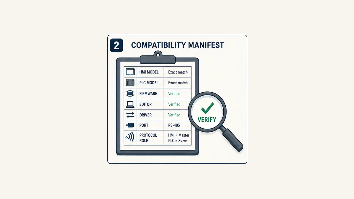
| Compatibility surface | Record exactly | Failure prevented |
|---|---|---|
| HMI | complete DOP catalog number and hardware revision | compiling for a screen, port set or resolution that is not installed |
| HMI firmware/runtime | as-found and intended revision | unsupported project/runtime combination or changed driver behavior |
| HMI editor | DIAScreen, controlled DOPSoft 4, DIAWebDesigner or another exact supported route | opening a legacy project in the wrong generation of tool |
| PLC | complete DVP/AS/AH catalog and CPU revision | assigning devices or instructions that do not exist on the target |
| PLC software | ISPSoft, WPLSoft or another exact supported tool and version | changing project format or download behavior accidentally |
| driver | exact displayed controller/driver name and revision | using a generic Modbus map when the project expects Delta device names |
| physical port | HMI COM number and mode; PLC built-in/module port | wiring RS-485 to an RS-232-only configuration or the wrong connector |
| protocol role | HMI requester/master/client; PLC responder/slave/server for this design | configuring both endpoints to wait or creating two active masters |
| settings | baud, data bits, parity, stop bits, station/node ID and timeout | “almost matching” configurations that never produce a valid response |
| controlled documents | manual title, document/revision and page for each setting | copying a terminal or menu from a different model |
Scope the documented teaching pair
Delta's DOP-107CV/EV installation sheet documents distinct interfaces for those exact panels. It shows COM1 as RS-232, COM2 as RS-232/RS-485 and COM3 as RS-422/RS-485; the DOP-107EV also has 10/100 Ethernet, while the DOP-107CV does not. That evidence is safe for understanding the pair, but it is not permission to apply the same connector pinout to another DOP model.
Delta DVP-SS2 literature identifies Modbus ASCII/RTU communication support and built-in serial interfaces. The exact DVP-SS2 operation manual must still determine the port, terminal designation, supported framing, station setup and special-register configuration on the installed CPU. If the target is a DVP-ES2, SA2, SE, SX2, ES3, AS or an expansion communication module, rebuild the manifest for that target.
For a new purchase, verify lifecycle and regional availability rather than treating the DOP-107EV example as a current recommendation. For a brownfield project, capture the existing editor, firmware and project backup before converting anything.
Decide the connection method and device roles
Native Delta driver over serial
Where the exact HMI editor includes a compatible Delta DVP controller driver, it may let HMI objects reference PLC devices such as M100 or D100 directly. The driver still uses a serial protocol and requires a matching electrical layer, COM configuration and PLC station. “Native” does not remove addressing; it packages the translation in a vendor driver.
This is the simplest route for the worked example because both endpoints are Delta products and the tag table can retain recognizable DVP device notation. Capture the driver name exactly as the editor displays it. Do not substitute a similarly named PLC family without checking its supported models and notes.
Generic Modbus RTU
A generic Modbus master driver can be appropriate when both exact devices support the required mapping and the project owns a formal Modbus data contract. In that case, record data model, function code, protocol offset, displayed 4xxxx or 0xxxx notation, width, signedness, word order and access. A DVP device number is not automatically the number an HMI expects in Modbus notation.
The Modbus Application Protocol defines coils, discrete inputs, input registers and holding registers and uses zero-based addresses inside a request. HMI tools often display human-readable references with a base or type prefix. Treat the HMI's display convention and the actual protocol offset as separate fields. Use the Delta PLC Modbus addressing guide when a generic map is required.
Ethernet is a different configuration branch
If the exact HMI and PLC or PLC communication module support an approved Ethernet driver, use an Ethernet-specific manifest: both IP addresses, subnet, route/VLAN, driver service, controller path or station/unit mapping, port where applicable, timeout and access controls. Do not carry RS-485 parity, termination or COM assumptions into the Ethernet design. Conversely, an HMI Ethernet socket does not prove that the PLC model offers a compatible Ethernet service.
| Route | Strong fit | Mandatory proof | Common trap |
|---|---|---|---|
| Delta controller driver over RS-485 | compatible DOP and DVP pair with a short controlled serial segment | exact driver support, port mode, wiring, framing, station and D/M device behavior | selecting the right PLC family but the wrong HMI COM port |
| generic Modbus RTU | explicit interoperable register/coil contract | function, offset convention, width, word order, timing and electrical layer | entering D100 as 40100 without verified translation |
| supported Ethernet driver | compatible Ethernet-capable HMI and PLC/module | IP identity, service/path, route, security and capacity | assuming every DOP or DVP variant has Ethernet |
| gateway | legacy/mixed interface with no approved direct route | both endpoint contracts plus translation, buffering and loss behavior | a healthy HMI-to-gateway link hiding a failed gateway-to-PLC side |
Worked RS-485 configuration: DOP HMI to DVP PLC
Step 1: make the physical layer unambiguous
Disconnect and work only under the site's electrical and hazardous-energy procedures. Confirm supply ratings and protective wiring from the exact installation sheets before connecting communications. RS-485 communication wiring is not a substitute for protective earth, safe isolation or a machine safety circuit.
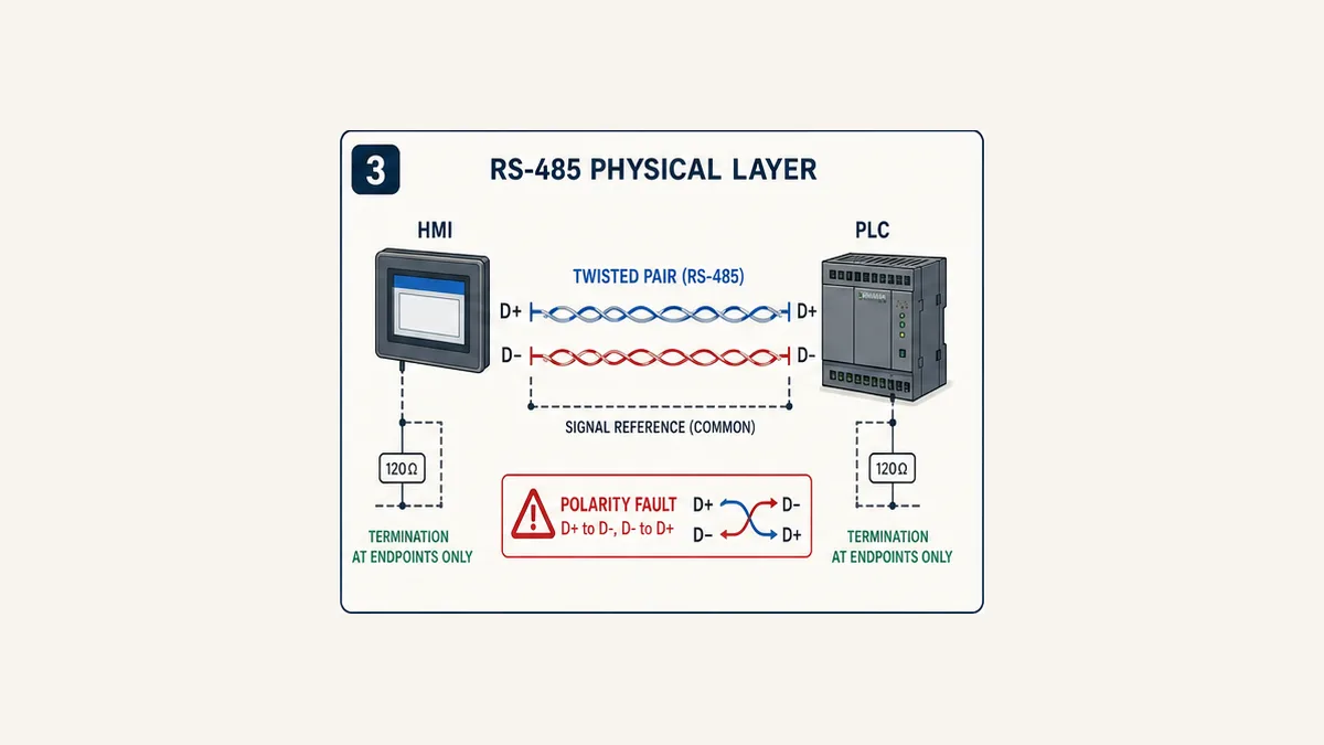
For the teaching trunk, select an RS-485-capable HMI COM interface and the verified PLC RS-485 interface. Connect the positive data terminal to the corresponding positive terminal and the negative terminal to its corresponding negative terminal using the terminal names in both exact manuals. Vendor A and B labels are not consistently interpreted across all products, so a remembered letter pair is weaker evidence than the documented D+/D- or equivalent polarity for the specific devices.
Use an appropriate twisted pair and the required reference/shield treatment from the hardware and site design. Keep the bus as a trunk rather than an uncontrolled star. Termination and bias are properties of the whole segment: install only the values and locations required by the manuals and topology. Do not add a termination resistor to every node because one forum diagram shows it.
Step 2: assign one coordinated serial profile
The following profile is deliberately a teaching choice. It is useful because every field is explicit. Before applying it, confirm both endpoints support it and preserve the as-found settings.
| Parameter | Worked value | Verification rule |
|---|---|---|
| electrical mode | two-wire RS-485 | exact COM/PLC port must support and be configured for it |
| application protocol | Modbus RTU through the selected compatible Delta driver | driver notes and PLC port manual govern |
| HMI role | master/requester | only one active master on this simple segment |
| PLC role | slave/responder | station must be unique on the segment |
| PLC station | 1 |
match HMI connection configuration; do not reuse another node ID |
| baud rate | 19,200 bit/s |
both ends identical |
| data bits | 8 |
both ends identical |
| parity | even | both ends identical |
| stop bits | 1 |
both ends identical |
| HMI timeout/retry | start from exact driver guidance, then measure | retries must not hide overload or extend a command beyond its valid context |
Avoid the habit of changing baud, parity, station and wiring at the same time. Record the original profile, change one controlled variable and repeat one defined read test. A valid response frame is stronger evidence than a generic “connected” lamp.
Step 3: configure the HMI connection
In the supported HMI editor, create or inspect the communication connection. DOPSoft documentation shows communication settings in the project workflow, while current DIAScreen documentation uses its own current communication-settings route. Menu labels can move between versions, so the durable sequence is:
- select the exact HMI target;
- select the exact compatible Delta controller driver;
- select the physical HMI COM port and RS-485 mode;
- enter the coordinated serial framing and PLC station;
- record timeout, retry and any driver optimization setting;
- compile the HMI project and resolve warnings;
- verify the selected target still matches the physical panel before transfer.
Do not configure two HMI connections against one physical COM port unless the driver documentation explicitly supports the required multidrop arrangement. Do not reuse an internal HMI control/status block range as application data. Delta support notes that the control block is important and recommends that PLC logic not use its addresses; reserve and document every system block used by the HMI.
Step 4: configure the PLC port
In the exact DVP programming environment and CPU manual, configure the selected port for the same mode, protocol, station and framing. Record whether the settings are project parameters, special devices, switches, retained values or another target-specific mechanism. Then establish when they take effect: immediately, after program transition, after power cycle or after another documented action.
Before downloading, back up and compare the PLC project and current parameter state. A communication “fix” that overwrites an unknown running configuration can disconnect another device or alter unrelated behavior. On a new bench target, initialize only the reviewed communication parameters and prove that the CPU is in the expected mode.
Step 5: prove one read before creating screens
Reserve a benign PLC word such as the worked D120 heartbeat and increment it slowly in controlled logic. Bind one HMI numeric display to that device through the selected connection. The test passes only if the value changes in the PLC monitor and the HMI shows the same sequence without unexplained freezes. A constant zero is weak evidence: it can result from correct communication, an unchanging source, a wrong address that reads zero or a stale display.
After that known read, prove a Boolean, signed negative value, upper-range integer, scaled value and any required 32-bit type separately. Delta HMI search/find support can help locate every object using a PLC device before an address changes; use the project cross-reference rather than manually inspecting screens.
Live mini-lab
Try it: press START, then STOP
A stop-dominant seal-in rung: START latches the motor output through its own contact, and STOP breaks the circuit.
Watch the output lamp: it stays on after START until you press STOP.
Free to start · runs in your browserOpens plcsimulationsoftware.com — same team
Build a controlled Delta tag and data map
Separate request, accepted state and physical feedback
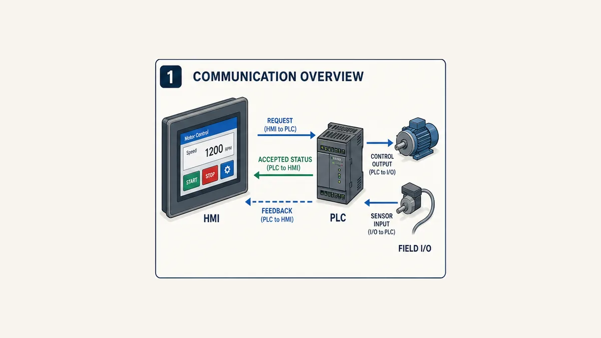
The HMI should not write a physical output such as Y0 or an internal command coil that bypasses application logic. It should write a request area. The PLC validates mode, user/process authority, range and permissives, then owns the command and reports actual feedback.
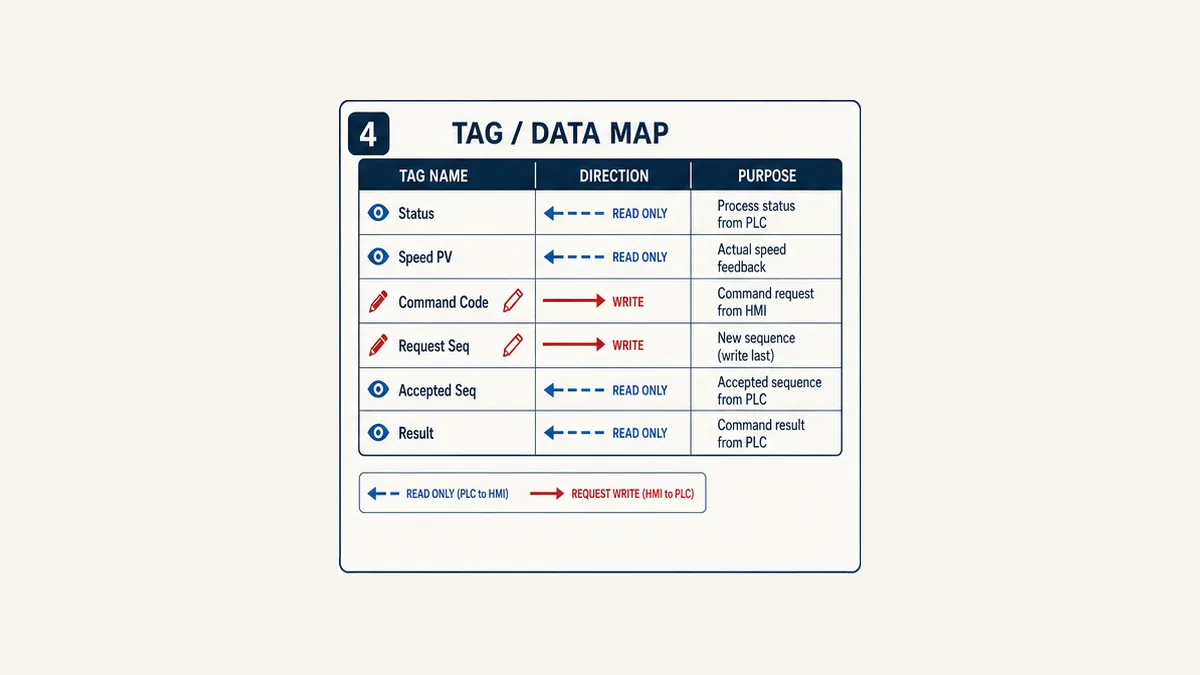
This worked map uses DVP device names because the example assumes a compatible native Delta driver. The numbers are a teaching allocation and must be cross-referenced and reserved in the actual PLC/HMI projects. A generic Modbus project requires an independently verified translation.
| PLC device | Stable interface name | Direction from HMI | Type/scale | Owner and rule |
|---|---|---|---|---|
M100 |
MotorReady |
read | Boolean | PLC-calculated permissive summary; HMI never writes |
M101 |
MotorRunning |
read | Boolean | PLC/field-feedback state, not button animation |
M102 |
MotorFaulted |
read | Boolean | PLC first-out/effective fault summary |
D100 |
SpeedRequest_x0_1Hz |
write request | signed word, 0.1 Hz | HMI candidate; PLC range-checks before use |
D101 |
SpeedActive_x0_1Hz |
read | signed word, 0.1 Hz | PLC accepted setpoint |
D102 |
SpeedPV_x0_1Hz |
read | signed word, 0.1 Hz | qualified drive/process feedback |
D110 |
CommandCode |
write request | enum word | 0 none, 1 start, 2 stop, 3 reset; sequence written last |
D111 |
RequestSequence |
write request | unsigned sequence | changes once for each deliberate transaction |
D112 |
AcceptedSequence |
read | unsigned sequence | PLC returns the last transaction it evaluated |
D113 |
CommandResult |
read | enum word | pending, accepted, rejected-mode, rejected-permissive, invalid-value or other defined result |
D114 |
ExecutionState |
read | enum word | idle, starting, running, stopping, done or faulted |
D120 |
PlcHeartbeat |
read | counter word | slow changing evidence that the group is fresh |
D121 |
InterfaceRevision |
read | unsigned word | expected PLC–HMI contract revision |
Use fixed point before introducing uncertain word order
The worked speed values use signed 16-bit tenths of hertz: the transferred value 425 means 42.5 Hz. That does not prove the drive or PLC already uses this representation. It gives the interface one testable convention and avoids 32-bit word-order ambiguity in the first commissioning stage.
If the application needs a 32-bit integer or floating-point value, prove width, word order, byte order where exposed, signedness and scaling with distinctive diagnostic patterns. Do not “fix” a wildly wrong float by multiplying it until it looks reasonable. Compare the PLC source words, transferred words and HMI type.
| Representation fault | Symptom | Controlled proof | Correction |
|---|---|---|---|
| signed versus unsigned | -1 appears as 65535 |
publish safe negative and boundary values | use the same signed type or explicit conversion |
| wrong 32-bit word order | float is tiny, huge or unstable | inspect two raw words for known values | configure and document verified word order |
| scaling twice | value is ten or 100 times expected | compare raw, PLC engineering and HMI display | apply scaling in exactly one owned layer |
| one-address shift | adjacent plausible value appears | place distinct test values in neighboring devices | correct driver notation/offset |
| stale last-good data | normal-looking value freezes | compare heartbeat and maximum age | show stale/unknown and qualify controls |
Budget polling around contiguous groups
Contiguous blocks can reduce serial requests, but grouping must not sacrifice meaning or access control. Put fast operational status, slower settings, alarms/history and transaction data into documented scan classes. Hidden screens should not continue polling every diagnostic device at the fastest interval unless the runtime and design require it.
Measure actual update age under the busiest screen, alarm/history activity and any other serial clients. Increasing baud or reducing timeout before measuring errors can make marginal wiring less stable or create retry storms. The right refresh rate is the slowest one that still supports the operator's decision and the process requirement.
Make HMI commands acknowledged transactions
Why a momentary start bit is fragile
A short HMI pulse can turn on and off between PLC observations, especially across serial polling. A lost release write can leave a request true. A reconnect can make it uncertain whether the PLC saw the old command. A button changing color proves only the screen's local state unless it is bound to PLC acknowledgement or physical feedback.
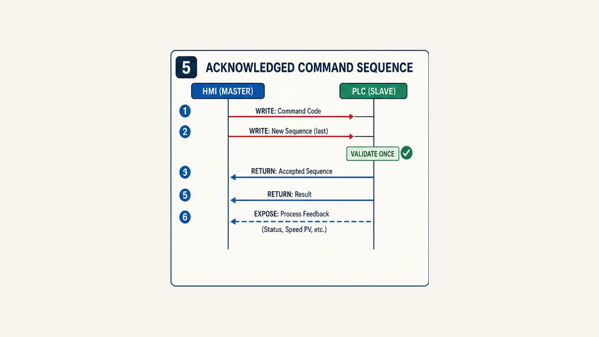
For the worked pattern, the HMI writes CommandCode first and then writes a new RequestSequence last. The PLC detects a new sequence, captures the associated request, validates it once, stores the same value in AcceptedSequence, and publishes a result. The HMI does not send another transaction until the current sequence is reconciled or deliberately abandoned under a defined workflow.
| Phase | HMI behavior | PLC behavior | Operator evidence |
|---|---|---|---|
| prepare | validate local entry and display intended action | no new action | confirmation text shows exact request |
| submit | write command/value fields, then change sequence last | detect new sequence and capture the candidate | pending state tied to sequence |
| decide | retain pending transaction | check mode, range, permissives and authority; acknowledge accepted/rejected once | accepted or bounded rejection reason |
| execute | monitor state without repeating request | run ordinary application sequence and timeout logic | starting/running/stopping/faulted state |
| prove | display PLC result and actual feedback | expose field/process outcome separately | success only when defined feedback is true |
| recover | reconcile pending sequence after reconnect | expose last accepted sequence and current truth | uncertain actions are not silently repeated |
Handle wrap, multiple writers and restart
Define sequence width and wrap explicitly. Equality and “new request” logic must remain correct when the maximum value rolls over. On PLC restart, do not execute retained request data merely because it is nonzero. Reconcile initialization state, interface revision, last accepted sequence and current machine truth.
One interface should have one transaction writer. If a second HMI, SCADA client or service can issue commands, give it an arbitration design or independent request slot and identity. Two clients writing the same code and sequence words can construct a mixed transaction that neither intended.
Stop behavior still follows the validated control design. A communications timeout must not become an improvised emergency stop. Safety functions and hazardous-energy isolation require their own approved architecture and lifecycle.
Build the HMI screen around state and evidence
Objects for the worked motor screen
Create a status header with connection/freshness, interface revision and current PLC mode. Provide Start, Stop and Reset request controls only where the ordinary control narrative permits them. Show SpeedRequest, SpeedActive and SpeedPV as three different values. Show ready, running, fault, pending command, accepted sequence, execution state and rejection reason.
Use text and shape in addition to color. A stale or bad value should not retain the same visual treatment as a live value. Disable or qualify request entry when the interface revision is wrong, heartbeat age exceeds the accepted limit or the connection is unavailable, but retain PLC-side validation because an object property is not a process interlock.
For numeric entry:
- state the engineering unit next to the value;
- constrain display and input format to the documented type;
- validate the candidate in the HMI for usability and again in the PLC for authority;
- show the active value returned by the PLC;
- expose why a candidate was clamped or rejected; and
- log the user/action/result where the selected product and site policy support it.
Compile and transfer each project separately
Compile the HMI project before transfer and confirm the project target matches the panel. Delta's older USB-download FAQ emphasizes compiling and matching the selected HMI type, while current DIAScreen support has its own transfer workflow. Treat these as version-specific evidence, not one timeless menu recipe.
Compile the PLC project and review differences before download. Transfer HMI and PLC changes as separately identified release items, then record the exact compatible pair. If communication breaks after only one side changes, compare the interface revision, driver, port parameters and tag map before changing physical wiring that was already proven.
Commission the connection in layers
Eighteen acceptance tests
The downloadable matrix includes expected HMI state, PLC state and evidence fields. Adapt it to the risk assessment and site procedure.
| ID | Test | Expected result |
|---|---|---|
| DH-01 | verify model/editor/firmware/driver manifest | every item matches the installed, controlled target |
| DH-02 | inspect isolated wiring and topology | port mode, polarity, reference, shield and termination match controlled documents |
| DH-03 | compare serial profiles | protocol, role, station, baud and framing match exactly |
| DH-04 | read changing PlcHeartbeat |
HMI sequence follows PLC without unexplained freeze |
| DH-05 | read Boolean status | known PLC transitions match object state and text |
| DH-06 | prove signed and scaled word | negative/boundary/test values render exactly once-scaled |
| DH-07 | prove any 32-bit value | width and word order pass several diagnostic values |
| DH-08 | submit valid speed request | PLC accepts candidate and returns active value |
| DH-09 | reject out-of-range speed | PLC returns bounded reason and active value remains valid |
| DH-10 | submit valid Start transaction | matching sequence accepted once; running completes only on defined feedback |
| DH-11 | submit Start without permissive | request rejected or held exactly as designed; no output bypass |
| DH-12 | repeat the same sequence | PLC does not execute a duplicate transaction |
| DH-13 | disconnect before PLC receipt | HMI reports uncertain/not accepted and does not infer execution |
| DH-14 | disconnect after PLC acceptance | reconnect reconciles accepted sequence and actual state without auto-repeat |
| DH-15 | restart HMI with pending request | no duplicate action; current PLC truth replaces local animation |
| DH-16 | restart PLC | retained/non-retained values and stale state follow specification |
| DH-17 | open busiest screen and alarm/history load | measured update age and retry rate remain within accepted limits |
| DH-18 | inject one documented fault and restore | first failed boundary is visible; normal, loss and restart regression still pass |
Record evidence, not only pass/fail
Retain HMI and PLC project hashes/revisions, exact settings, controlled manuals, wiring inspection, cross-reference exports, screenshots, runtime/PLC monitored values, serial diagnostic captures where authorized, measured age, request/ack sequences, injected-fault steps, result, deviations and restoration. Redact credentials or sensitive architecture before sharing records.
A simulator can strengthen the logic portion before a field test. Use the Modbus simulator lab to practise register/offset reasoning, request-response behavior, exceptions, stale values and one-variable-at-a-time fault isolation. It does not emulate a Delta DOP runtime, Delta driver, DVP port, D/M device mapping, serial electrical layer, installed I/O, process, cybersecurity configuration or safety function. Measure lab click, start, registration and paid conversion together so useful technical engagement—not raw referral volume—determines whether this CTA remains.
Troubleshoot Delta HMI communication from the bottom up
Find the first failed boundary
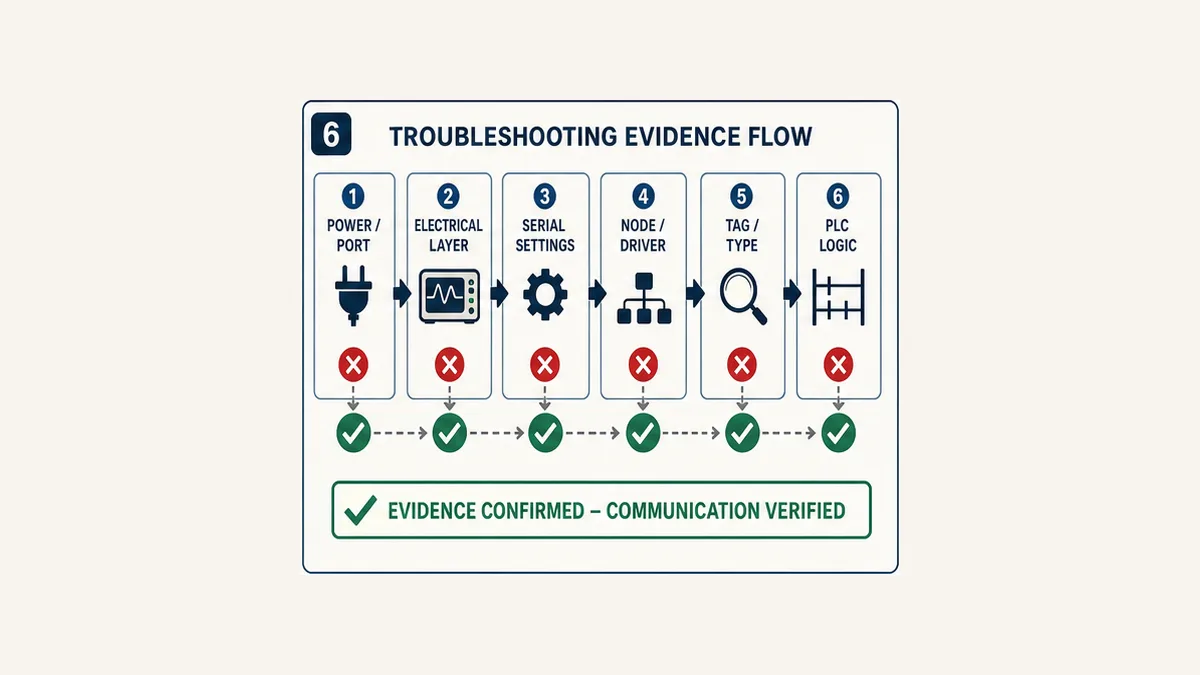
Build one timeline: HMI object, HMI device/tag value, driver/connection state, serial request and response evidence, PLC communication state, PLC source device, application logic, physical command and process feedback. Stop at the first mismatch. A red HMI object is the last visible symptom of many different faults.
No tags communicate
Prove that both devices are powered and in the expected modes. Confirm the HMI project was compiled for the installed panel and uses the physical COM interface that is actually wired. Compare electrical mode, polarity, topology and reference. Compare protocol, role, station, baud, data bits, parity and stop bits character by character.
Then inspect whether the HMI is transmitting requests and whether the PLC replies, using supported diagnostics or an authorized capture method. Requests with no response point toward wiring, port mode, station, PLC protocol/configuration or a failed responder. No requests point toward HMI project, driver, screen/tag activation or port selection. Corrupt or exception responses narrow the problem further.
Some tags work but one value is wrong
The common transport is probably healthy. Compare the exact HMI device reference with the PLC source and cross-reference. Confirm driver notation, type, width, signedness, word order, scaling and read/write access. Use distinctive controlled values in neighboring addresses. Check whether another PLC instruction, HMI object, recipe, data exchange function or indirect move also writes the device.
If a value changes correctly in the PLC monitor but not at the HMI device/tag monitor, remain at the communication/mapping boundary. If the HMI device value is correct but the screen is wrong, inspect object conversion, formatting, animation and visibility. Do not alter baud rate to repair one mis-typed value while hundreds of other reads work.
Reads work but writes do not
Verify the object points to the request device, not read-only status. Check user level and object enable state, but also inspect the raw PLC request device. If it never changes, investigate the HMI object, access/driver and write response. If it changes and is immediately restored, find the PLC or second-client writer. If the request and sequence arrive but no action follows, inspect AcceptedSequence, CommandResult, mode, permissives and application state.
This distinction prevents a common error: defeating a PLC interlock because the HMI button “does nothing.” A process rejection is not a communication failure.
Communication is intermittent or slow
Measure framing/CRC errors, retries, timeouts, request rate, response time and age per group where the products expose them. Inspect cable routing, shield/reference practice, termination/bias, polarity, loose terminals, topology and noise sources under representative machine conditions. Compare performance with the busiest HMI screen, history/alarm collection and any other clients active.
Avoid blindly increasing retries. A long retry chain can make a failed screen appear frozen, delay operator feedback and multiply load. Reduce scattered fast polling, group appropriate contiguous data, slow noncritical values and correct the physical fault. Use the exact product limits rather than a universal node count or cable-length number.
Communication fails after download or migration
Compare the before/after target model, firmware, editor version, driver, COM assignment, serial profile, station, HMI system block, PLC device map and interface revision. If migrating from DOP-B/DOPSoft 2, follow Delta's controlled DOPSoft 4 conversion route only where the FAQ says the legacy file is compatible, then revalidate every screen object and target-specific function. A successful file open is not acceptance evidence.
| Symptom | Prove first | Then inspect | Do not assume |
|---|---|---|---|
| no values | HMI requests and PLC replies | physical layer, profile, station, driver and port | the remembered cable pinout fits this model |
| all values zero | changing known PLC source | target connection and mapped device | zero proves communication |
| one value wrong | raw source and raw HMI tag | notation, address, type and scaling | whole bus is noisy |
| reads okay, writes fail | raw request device | object access, second writer, PLC validation | an interlock should be bypassed |
| works until busy screen opens | request rate and update age | poll groups, retries, history and other clients | faster polling solves capacity |
| fails after project transfer | compatibility and parameter diff | target, driver, interface revision and device map | hardware failed simultaneously |
| reconnect repeats action | request/accepted sequence trace | restart and reconciliation logic | momentary bits are transaction-safe |
Security, safety and lifecycle boundaries
Keep the PLC/HMI interface narrow: status read-only, settings constrained, commands validated and engineering-only devices unavailable to ordinary screens. Use the product's supported accounts and protected transfer methods, the site's OT segmentation and access controls, controlled backups and restoration tests. Do not expose a DOP or DVP communication service directly to the public internet.
Human permission and process permission are separate. The HMI may authenticate an operator and allow a request; the PLC still evaluates current mode, permissives and equipment state. Neither decision is a safety function. Emergency stopping, guarding, safe motion and hazardous-energy isolation require the approved safety architecture and site procedure. An HMI may display their state but must not be the sole protective device.
Treat legacy software as a lifecycle risk. Preserve install media, licence evidence, project source, runtime/firmware files, known-good backups, conversion notes and a tested restore path according to vendor terms and site policy. Never download an unofficial editor merely because a forum link is easier to find than Delta's Download Center.
Delta HMI communication answer map
Setup and software questions
- How do I connect a Delta HMI to a Delta PLC? Match exact models and software, select a supported Delta PLC driver, connect a verified RS-485 or Ethernet interface, match every endpoint setting, prove one changing read and then implement a controlled tag map.
- Which software programs a Delta HMI? It depends on family and project lineage. Current Delta pages associate DOP-100 with DIAScreen and DOP-300 with DIAWebDesigner; supported controlled DOPSoft 4 projects still exist, while DOPSoft 2 is retired. Verify the exact panel in Delta's current Download Center.
- Can DOPSoft 2 program a new DOP-100? Delta says DOPSoft 2 is no longer updated/downloadable and provides a DOPSoft 4 migration route for compatible DOP-B files. Conversion and target switching still require complete revalidation.
- Does every Delta HMI have Ethernet? No. Hardware is model-specific. The documented DOP-107EV has Ethernet; the DOP-107CV does not, and other product families have their own configurations.
RS-485 and addressing questions
- What RS-485 settings should a Delta HMI and DVP PLC use? Use any framing and speed supported by both exact devices and approved for the segment, then make the values identical. The
19,200 8-E-1, station 1profile here is a teaching choice, not a factory default. - Which Delta HMI COM port supports RS-485? It varies by model. The DOP-107CV/EV sheet documents RS-485 capability on COM2 and COM3 with different selectable modes; inspect the exact installed model before wiring.
- Should the HMI be master or slave? In the simple worked polling architecture, the HMI is master/requester and the PLC is slave/responder. A different architecture is possible only when the exact products and design support it.
- How do Delta D registers map to Modbus holding registers? The answer depends on the selected HMI driver and its notation/translation. Keep DVP device, Modbus data model, zero-based protocol offset and displayed reference as separate verified fields.
Troubleshooting questions
- Why is a Delta HMI not communicating with the PLC? Check power/target, exact COM port and electrical mode, RS-485 polarity/reference/topology, protocol role, station, baud/framing and driver before editing the tag map.
- Why does a Delta HMI show zero for every PLC value? Prove a changing known PLC source. Zero may be valid, stale, uninitialized or the result of a wrong target/address; it is not communication proof.
- Why do Delta HMI reads work but writes fail? Trace the raw request device. The object may be read-only or blocked, another writer may restore the value, or PLC validation may correctly reject the request.
- Why does Delta HMI communication become intermittent? Capture errors, retries, timing and load, then inspect the RS-485 physical layer and polling design. Noise, reference, topology, termination/bias, loose wiring and excessive fast polling can create similar symptoms.
These answer units describe an engineering method, not universal terminal assignments or production settings.
Frequently asked questions
What is Delta HMI communication?
Delta HMI communication is the configured exchange of process status, measurements, settings and operator requests between a Delta touch-panel runtime and a PLC or other controller. Reliable communication includes compatible products and software, physical/network setup, protocol roles, tag meaning, quality/freshness, command validation and acceptance evidence.
How do I connect a Delta DOP HMI to a DVP PLC?
Record exact model and software versions, select a compatible Delta DVP driver, choose a supported RS-485 or Ethernet port, match endpoint settings, reserve a controlled PLC data area and prove one changing read. Add each type and supervised write separately, then test loss, restart, rejection and full screen load.
What software is used for Delta HMI programming?
The answer is product- and project-specific. Delta's current DOP-100 page identifies DIAScreen, DOP-300 uses DIAWebDesigner, and Delta still documents controlled DOPSoft 4 workflows. DOPSoft 2 is retired. Verify the exact HMI, firmware, project lineage and current supported download in Delta's official product and Download Center pages.
Can I open a DOP-B project for a DOP-100 HMI?
Delta's migration FAQ says compatible legacy files can be opened in DOPSoft 4 and the HMI type changed to a DOP-100 target. That is a migration starting point, not proof of complete compatibility. Revalidate objects, fonts, scripts, recipes, alarms, communication drivers, system blocks, ports, transfer and restart behavior.
Which cable connects a Delta HMI to a Delta PLC?
There is no universal Delta HMI-to-PLC cable. The required connector and conductors depend on both exact ports and whether the design uses RS-232, two-wire/four-wire RS-485/RS-422, Ethernet or another interface. Use both installation manuals and an approved cable drawing; never infer connector pins from the family name.
What are the correct RS-485 settings for a Delta HMI?
Both endpoints must use a mutually supported and identical protocol, baud, data bits, parity and stop bits, with a unique PLC station. The worked 19,200 8-E-1, station 1 settings are an explicit lab profile, not universal defaults. Preserve and verify the installed configuration before changing it.
Should a Delta HMI be the Modbus master?
For ordinary HMI polling of a DVP PLC in the worked serial architecture, yes: the HMI initiates requests and the PLC responds. Do not place two masters on a simple RTU segment without an explicitly supported arbitration design. Delta products can support other roles in other applications, so record the exact driver and architecture.
Why is my Delta HMI connected but not updating values?
A driver or port can appear active while a device reference, station, type, screen group or source is wrong. Prove a known changing PLC word, inspect the raw HMI tag/device value, compare exact address notation and type, and use heartbeat age rather than relying on a connection icon or constant zero.
Why does my Delta HMI display the wrong number?
Compare PLC source, transferred raw value and HMI display. Common causes are the wrong D/M device, a one-address translation error, signed/unsigned mismatch, 32-bit word order, scaling applied twice, integer truncation or stale data. Test several distinctive safe values before changing live process scaling.
Why can the Delta HMI read PLC values but not write them?
The object may point to status rather than a request area, access/user state may block it, the driver may reject the write, another writer may overwrite it, or PLC logic may reject the request because mode, range or permissives are invalid. Trace the raw request, sequence, acknowledgement and result before changing interlocks.
Should a Delta HMI button write directly to a PLC output?
No for ordinary machine commands. Write a controlled request, let PLC logic validate and own the command, and show physical/process feedback separately. Direct output writes can bypass application sequencing and leave the screen indicating success without verified field action.
How can I stop a Delta HMI command from repeating after reconnect?
Use a request code plus a changing sequence or toggle, return the accepted sequence and result from PLC logic, and reconcile those values after reconnect before issuing another request. Define wrap, restart and multiple-writer behavior. A short momentary bit does not provide those guarantees.
How do I troubleshoot intermittent Delta PLC and HMI communication?
Capture requests/responses or supported error counters, retries, response time and tag age under representative load. Inspect port selection, RS-485 polarity/reference, shield, topology, termination/bias, loose terminals and noise. Then review polling groups and other clients. Change one variable and repeat the same test.
Can I test Delta HMI communication in a simulator?
A generic simulator can help test Modbus addressing concepts, data contracts, command handshakes, stale states and diagnostic reasoning. It cannot prove Delta driver compatibility, exact DOP/DVP firmware, COM terminal wiring, HMI runtime behavior, target device mapping, real I/O, network load, cybersecurity controls or safety functions. Repeat acceptance tests on approved hardware.
Sources, review scope and limitations
This guide was last reviewed on 31 August 2026. It is a model-scoped engineering and troubleshooting method, not a cable drawing, project file, safety specification or permission to connect to operating equipment. Product availability, downloads, menus, firmware, drivers, supported controllers, system blocks and transfer behavior can change. The exact official documents for the installed catalog numbers take precedence.
Primary and first-party sources reviewed:
- Delta: Touch Panel HMI product portfolio — current DOP family and product-selection boundary.
- Delta: DOP-100 Series product page — current DOP-100 features, model/port variation and DIAScreen software statement.
- Delta FAQ: DOP-B replacement and project migration — DOP-B/DOPSoft 2 lifecycle and compatible DOPSoft 4 conversion route.
- Delta: DOPSoft 4 User Manual — DOP-100 project and communication-setting workflow for applicable DOPSoft 4 projects.
- Delta FAQ: DIAScreen communication settings — current DIAScreen-era configuration context.
- Delta: eComm User Manual — DIAScreen communication-settings and supported-model boundaries for the documented feature.
- Delta: DOP-107CV/EV Installation Sheet — exact power, COM interface and DOP-107EV Ethernet distinctions for the teaching HMI.
- Delta: DVP-SS2 Series product page — product-family context for the teaching PLC.
- Delta: Industrial Automation Product Catalogue — documented DVP communication capability and family-selection context.
- Delta: HMI Connection Manual — historical Delta-controller and generic Modbus driver concepts; example settings are not treated as current universal defaults.
- Delta: DVP Serial Communication Module Operation Manual — historical serial application and role evidence; its example profile is not prescribed here.
- Delta FAQ: Find read/write addresses in DOPSoft — project cross-reference/search workflow.
- Delta FAQ: HMI control and status blocks — system-block importance and PLC-address reservation warning.
- Delta FAQ: DOPSoft project download by USB — applicable compile and target-match requirements for the documented older workflow.
- Delta FAQ: transfer a DIAScreen project — current DIAScreen-era transfer workflow context.
- Modbus Organization: Modbus Application Protocol V1.1b3 — normative Modbus client/server transactions, data model, addressing and exceptions.
- Modbus Organization: Modbus over Serial Line Specification and Implementation Guide V1.02 — serial roles, framing and implementation guidance.
- OSHA 29 CFR 1910.147: Control of hazardous energy — United States hazardous-energy-control requirements; other jurisdictions and site rules may differ.
All six figures are original conceptual illustrations made for this guide. They deliberately omit vendor logos, exact terminals and project screenshots. They do not prove compatibility, define a safety function or replace target-specific manuals, an approved electrical drawing, risk assessment, controlled backups or supervised commissioning.
Now run it · free to start
Try an HMI exercise in your browser
Build a small operator screen from tags, pushbuttons and pilot lamps in a guest exercise. Free to start, nothing to install.
Ownership disclosure: PLC Programming IO and PLC Simulation Software are operated by the same publisher.
PLC Programming IO Editorial Team
Industrial automation education, references, and software testing
The PLC Programming IO Editorial Team publishes sourced industrial-automation education and documents how material is reviewed, tested, and corrected. A team byline means the publisher is responsible for the page; it does not represent a fictional person or imply an engineering licence.
Coverage:
- • PLC programming concepts and examples
- • Vendor software tutorials and comparisons
- • SCADA, HMI, protocols, and instrumentation
- • Training, careers, and reference material
Review standard:
- • Prefer primary and official sources
- • Record software versions when material
- • Separate tested facts from estimates
- • Publish material corrections
Important scope note
This site provides education, not project-specific engineering approval. Safety, code, and compliance decisions require a qualified person with access to the actual machine and jurisdiction.