Sequential Function Chart (SFC): Steps, Transitions and Examples
Design and test PLC sequences with SFC steps, transitions, actions, alternative and parallel branches, scan semantics, restart recovery and a worked batch-mixer example.
Review status: Primary-source technical review completed 30 August 2026 against IEC 61131-3:2025 and official Rockwell, Siemens, CODESYS, Beckhoff and Schneider documentation. Confirm actions, qualifiers, evaluation order and restart behavior in the exact controller and software version.
Direct answer: what Sequential Function Chart is
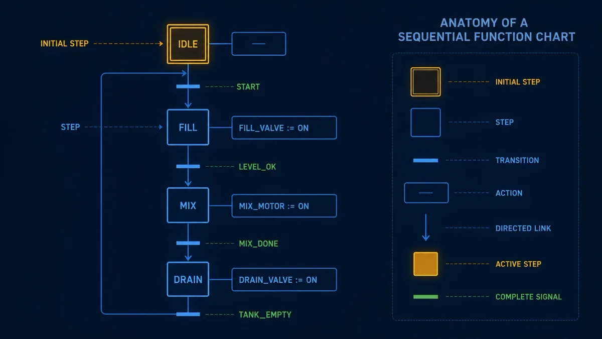
A Sequential Function Chart (SFC) organizes control behavior as active steps, Boolean transitions, associated actions and directed links. When the preceding step or steps are active and the next transition is satisfied, the chart changes its active-step state according to the target platform's execution rules. SFC is useful when the process is naturally described as phases: initialize, fill, heat, mix, inspect, transfer, clean and recover.
The current IEC 61131-3:2025 Edition 4 publication record describes Structured Text, Ladder Diagram and Function Block Diagram as the programming-language suite, with additional graphical and equivalent textual structuring elements for Sequential Function Chart. Older teaching material often calls SFC “one of five IEC languages.” That shorthand is not the current edition's formulation, and Instruction List has been removed from the current suite.
SFC does not eliminate the logic inside each phase. Step actions and transition conditions still need implementation, and vendors allow different action languages and editor behavior. SFC owns the coordination structure; reusable function blocks, ladder routines or Structured Text can own the detailed equipment behavior.
| SFC element | Meaning | Review question |
|---|---|---|
| initial step | defined active starting point after initialization | what physical and software conditions are safe at initialization? |
| step | a named phase that can be active | what is true while this phase is active? |
| transition | condition between steps or branch regions | is it necessary, sufficient, stable and observable? |
| action | behavior associated with a step | when does it start, continue, stop and reset? |
| alternative branch | one selected path among choices | if several choices are true, which has priority? |
| parallel branch | multiple paths activated together | what synchronizes their completion and what if one stalls? |
| jump or macro | navigation or hierarchical grouping where supported | can reviewers still see all reachable states and recovery paths? |
Decide whether the problem is actually sequential
SFC is strongest when operators and engineers already describe the process with named phases and allowed changes between them. A batch vessel has clear phases. A packaging machine has an index, clamp, process, inspect and discharge cycle. A utility plant has startup, warm-up, online, controlled shutdown and trip-recovery states.
Do not force every Boolean interlock into SFC. A motor seal-in, direct permissive chain or small three-state device may be clearer in ladder or a reusable equipment function block. Likewise, a mathematical algorithm remains a poor fit for boxes and transitions simply because SFC is available.
Convert the operating narrative into a state model first
Before opening the editor, write the normal phases, entry conditions, completion conditions, aborts, holds, timeouts and recovery decisions. Identify which operations may occur simultaneously and which must remain mutually exclusive. Ask operators what evidence distinguishes “waiting normally” from “stuck.”
| Narrative statement | SFC design surface | Evidence required |
|---|---|---|
| “Fill until target weight” | Fill step plus target-reached transition | valid scale, command proof, weight trend and timeout |
| “Heat while both feeds complete” | parallel heat and feed paths | independent completion state and synchronization |
| “If quality fails, divert” | prioritized alternative transition | inspection result validity and decision record |
| “Hold without losing the batch” | explicit hold policy or controlled state handling | retained phase, action response and resumption criteria |
| “Abort to safe condition” | reachable controlled-abort sequence | actuator response, energy/process boundary and operator authority |
| “Restart where we left off” | validated recovery path, not an automatic promise | physical-state reconciliation and permissive proof |
Keep equipment behavior below the sequence layer
The SFC should command a valve module to open and wait for OpenProven; it should not duplicate the valve's travel timer, output arbitration and feedback alarm in every step. This separation makes the sequence readable and lets the equipment block be tested independently.
Build steps and transitions that explain themselves
A step name should describe a stable phase, not an output coil. FillToTarget, HeatSoak and AwaitDischargeClear are more informative than Step12. Give every step an explicit purpose, active actions, expected completion evidence, maximum useful dwell time and possible exit paths.
Write transition conditions as proof of readiness to leave
“Time elapsed” is rarely enough. A transition from Fill to Mix might require target mass reached, measurement valid, inlet valves proven closed and no active abort. Separate process completion from permission to continue when both matter.
Good transition design is:
- necessary: the next phase must not begin without it;
- sufficient: all required conditions are present, not just one convenient signal;
- stable: noise or a one-scan flicker will not create an unintended transition;
- observable: a technician can tell which term prevented progress;
- bounded: unreasonable dwell time creates a useful diagnostic or controlled response;
- owned: one clear part of the program determines the result.
Avoid opaque transition expressions
A single expression containing twenty tags may compile, but it is difficult to commission. Build named intermediate conditions such as FillComplete, OutletReady, QualityAccepted and AbortRequired, then expose the false terms in diagnostics. Names are not enough by themselves; each must have a documented meaning and test.
Understand SFC scan execution
SFC editors animate active steps, which can create the illusion that the diagram flows continuously. A PLC still evaluates behavior in cycles or tasks. The precise ordering of step actions, IEC actions, transitions, step activation and deactivation is platform-defined.
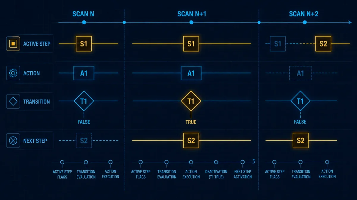
CODESYS documents an exact SFC processing sequence, including initialization, reset handling, action processing, transition evaluation and step activation. It also warns that the same action can execute multiple times in a cycle if it is associated through multiple active paths. Beckhoff TwinCAT documents similar editor and action considerations in its platform context. Rockwell provides a dedicated Logix 5000 SFC manual covering step, transition, action, pause and reset behavior.
Do not turn those examples into a universal IEC execution algorithm. The standard structures the language; the compiler and runtime documentation define the concrete behavior that your test must match.
Simple scan trace
Assume Fill is active, TargetReached changes from false to true, and the platform deactivates Fill and activates Mix according to its documented cycle semantics:
| Scan evidence | Fill active | Fill action | transition result | Mix active | What to verify |
|---|---|---|---|---|---|
| N before target | 1 | executes | 0 | 0 | fill output and target evaluation are correct |
| N+1 target appears | product-defined current active state | product-defined | 1 | product-defined activation point | exact order from runtime manual and trace |
| N+2 after change | 0 | no normal active action | next transition evaluated as applicable | 1 | entry/exit/active actions occur once as designed |
The table intentionally avoids pretending that all systems switch at the same point inside the scan. Run a small target-specific experiment with trace tags for active steps, transition values, action calls and physical outputs.
Entry, active and exit behavior are not interchangeable
An entry action typically executes once when a step becomes active, an active action while it remains active, and an exit action once as it deactivates. Exact support and timing vary. Use entry for one-time initialization only when repeating that initialization after pause, reset or online edit is understood. Use an active action for behavior that must remain serviced. Use exit for deliberate cleanup that will still run in every relevant abnormal path.
Design alternative and parallel branches correctly
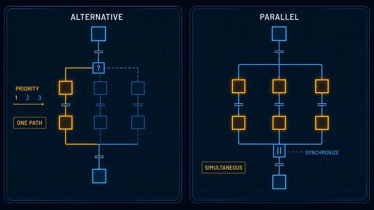
Alternative and parallel structures solve different problems. Confusing them can start two mutually exclusive paths or wait forever for a path that was never activated.
Alternative branches need explicit priority
In an alternative branch, more than one transition may be true on the same evaluation. CODESYS documents left-to-right evaluation for its alternative branches. Other products may use a configured order or different rule. Design conditions to be mutually exclusive where practical and document priority where simultaneous truth is possible.
For an inspection result, prefer named decisions such as:
AbortRequired— highest priority;InspectionInvalid— stop and request evidence;PartRejected— divert;PartAccepted— continue.
Do not place broad TRUE or timeout exits before more specific branches unless that priority is intentional and tested.
Parallel branches need synchronization and timeout policy
A parallel divergence activates several paths. A convergence should not proceed until the required paths reach their synchronization condition. Decide what happens if one branch completes early, one remains busy, one faults or an operator requests hold.
| Parallel-path condition | Required policy |
|---|---|
| all paths complete normally | synchronize and continue once |
| one path complete, one active | completed path remains in a defined wait state |
| one path faults | stop, hold or abort all affected work under a documented priority |
| one path times out | record the stalled path and first missing condition |
| hold requested | define whether each action freezes, stops or moves to a hold-safe state |
| abort requested | converge through a controlled abort design, not an accidental normal join |
Live mini-lab
Try it: press START, then STOP
A stop-dominant seal-in rung: START latches the motor output through its own contact, and STOP breaks the circuit.
Watch the output lamp: it stays on after START until you press STOP.
Free · no signup to try · runs in your browserOpens plcsimulationsoftware.com — same team
Worked SFC example: batch mixer
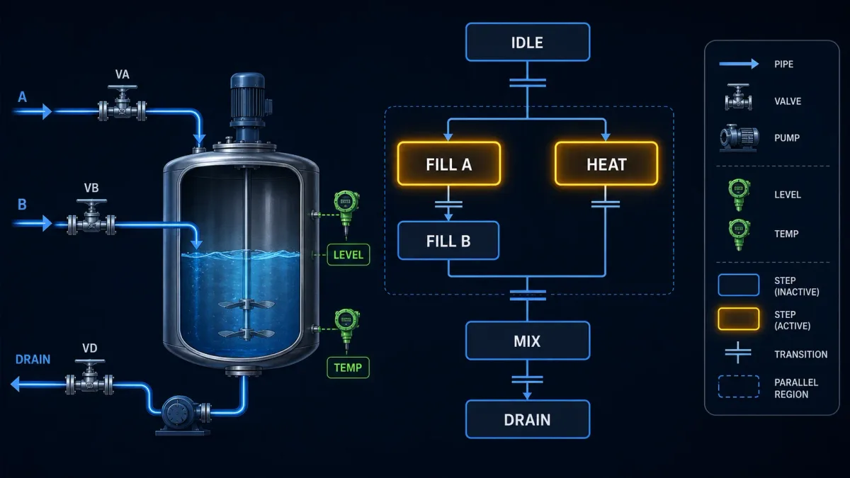
Consider a jacketed batch mixer with two ingredients, a heater, agitator and drain valve. The example is educational and omits the detailed safety instrumented functions, electrical design, recipe management and validated process controls required by a real plant.
Step and transition specification
| Step | Active commands | Completion evidence | Timeout or abnormal path |
|---|---|---|---|
Idle |
all process requests off; show ready state | valid recipe, vessel available, start accepted | reject start with reason |
Precheck |
request equipment readiness checks | drain closed, vessel empty or reconciled, sensors valid, permits present | hold for correction or abort |
FillA |
Ingredient A valve/pump module requested | valid weight contribution A at target and flow stopped | no-flow, overshoot or device fault |
FillB |
Ingredient B valve/pump module requested | valid weight contribution B at target and flow stopped | no-flow, overshoot or device fault |
Heat |
temperature-control module enabled | temperature reaches band and required soak completes | sensor invalid, heat failure or high limit |
Mix |
mixer requested at recipe speed | feedback at speed and mix duration complete | failed start, speed deviation or device fault |
Drain |
outlet path requested open and discharge enabled | vessel empty evidence stable for defined time | blocked discharge or invalid level |
Complete |
capture batch completion and release requests | downstream acknowledgment | bounded wait and operator resolution |
The two ingredient feeds might run in parallel if the process design permits them, while heating may start only after a minimum level or may run in a third parallel branch. That choice belongs to the process hazard and quality design, not to a generic SFC tutorial.
Example transition definitions
PrecheckComplete := RecipeValid
    AND VesselAvailable
    AND Drain.ClosedProven
    AND Weight.Valid
    AND Temperature.Valid
    AND SequencePermit;

FillAComplete := FeedA.TargetReached
    AND FeedA.FlowStopped
    AND FeedA.OutletClosedProven;

HeatComplete := Temperature.InBand
    AND HeatSoakTimer.Q
    AND Temperature.Valid;

AbortRequired := EmergencyProcessCondition
    OR FeedA.UncontrolledFlow
    OR FeedB.UncontrolledFlow
    OR Temperature.HighHigh;
Run Structured Text in the simulator
Names such as EmergencyProcessCondition are not a substitute for a safety design. A standard application SFC must not be treated as the sole risk-reduction layer where a safety function is required.
Commission the worked example in layers
First prove each equipment module with simulated or isolated feedback. Then prove each transition expression without changing physical outputs. Next run one path at a time, including timeout and invalid-instrument cases. Prove parallel completion and a fault in each branch. Finally run integrated recipes under the authorized commissioning plan and capture the actual sequence trace, alarms, operator messages and product acceptance results.
Action models and qualifiers require product documentation
SFC environments can associate actions with steps and offer qualifiers such as non-stored, set, reset, pulse, delayed or time-limited behavior. The exact qualifier set, notation, timing and interaction with entry/exit actions varies. CODESYS distinguishes IEC actions from step actions and documents how associations and qualifiers execute. TwinCAT provides entry, active, exit and action-association features. Schneider Machine Expert documents qualifiers, implicit variables and SFC flags.
| Desired behavior | Safer design question | Common implementation surface |
|---|---|---|
| command exists while step active | does it drop immediately on deactivation, hold or abort? | normal/non-stored active action |
| pulse once at activation | what happens after reset, restart or re-entry? | entry action or pulse qualifier |
| remain set after step exits | which reachable state always resets it? | stored/set and reset pair, used sparingly |
| begin after delay | is the delay reset on step loss; what if the step re-enters? | delayed qualifier or explicit timer |
| run for limited time | does physical completion override time? | time-limited qualifier or explicit state |
Stored actions are easy to start and easy to forget to reset. For critical outputs, explicit equipment commands and a visible ownership model are often easier to audit than widely separated set/reset associations. Never allow several active steps to write the same physical command without a documented arbitration layer.
Hold, pause, abort, reset and restart are separate requirements
These words are often used interchangeably in operating conversations, but they imply different state changes.
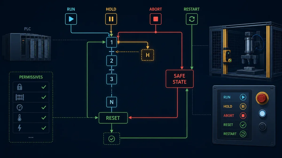
- Hold preserves the production context while actions move to a defined hold response. Some actuators may stop; others may need to continue maintaining temperature, pressure or position.
- Pause may mean freezing chart advancement, but freezing software does not freeze physics. The platform's pause behavior must be understood.
- Abort deliberately leaves the normal path and coordinates equipment toward a controlled process state.
- Reset clears specified latched conditions or reinitializes chart state only after its prerequisites are met.
- Restart begins a new cycle or a validated recovery sequence. It should not blindly re-energize outputs from retained step bits.
- Resume continues from a preserved phase after physical-state reconciliation.
Reconcile physical state before software state
After power loss or a long hold, the vessel may have cooled, a pneumatic cylinder may have drifted, a valve may have moved manually, material may have settled and downstream equipment may no longer be ready. Retaining the active step does not prove that the phase can continue.
Build a recovery assessment using trustworthy feedback: actual positions, valid instruments, device health, remaining material, recipe identity, elapsed hold time and operator authorization. Route ambiguous conditions to a recovery mode rather than forcing the normal transition true.
Define action response for every interruption
| Action type | Hold question | Abort question | Restart question |
|---|---|---|---|
| valve/feed | close, maintain or regulate? | how is uncontrolled flow stopped and proven? | is line primed or material reconciled? |
| heater | maintain band, ramp down or disable? | what independent high-limit protection exists? | are temperature validity and product limits satisfied? |
| mixer | continue, slow or stop? | could stopping create settling or thermal risk? | does restart require a ramp or mechanical check? |
| timer | freeze, reset or continue wall time? | which diagnostic records expiry? | is prior elapsed time still valid? |
| communication request | continue servicing, cancel or wait? | can the device confirm cancellation? | is the request safely re-armed? |
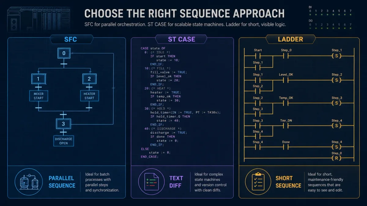
Compare SFC with ST CASE and ladder step sequences
Many sequences can be implemented in more than one language. Choose the representation that makes state, transition priority, abnormal paths and maintenance evidence easiest to review.
| Choice | Strong fit | Main caution |
|---|---|---|
| SFC | multi-phase coordination, parallel branches, online active-step visualization | vendor execution and action semantics; graphical diff workflow |
ST CASE state machine |
compact text review, data-heavy decisions, simple mutually exclusive states | parallel behavior and transition priority can become hidden |
| ladder step bits | short discrete sequence maintained by ladder-focused teams | duplicate step bits, scattered transitions and output ownership |
| reusable function block | repeated equipment behavior with a stable interface | do not hide the plant-wide coordination inside one black box |
Rockwell's September 2025 design considerations recommend SFC for high-level management, repetitive sequences, batch, motion sequencing and state machines in its Logix context. The same manual recommends ladder for maintenance-visible interlocking and FBD for continuous process/drive and loop control. That is a useful architecture prompt: use different languages for different responsibilities while keeping output ownership clear.
Vendor implementation map
Do not claim that “all major PLCs support SFC” without qualifying product, license and version. Support differs by controller family, engineering package and edition.
| Platform | Officially documented surface | Verify before design |
|---|---|---|
| Rockwell Studio 5000 Logix Designer | Logix 5000 SFC routines, steps, transitions, actions, pause/reset behavior | controller family, software edition/version, task and action rules |
| Siemens STEP 7 / TIA Portal | S7-GRAPH/SFC referenced in current programming style guidance | GRAPH availability/license, CPU support, supervision and interlock behavior |
| CODESYS Development System | SFC POU, steps, transitions, branches, jumps, macros, actions and implicit variables | runtime/compiler version, action model and processing order |
| Beckhoff TwinCAT 3 | SFC POU editor with steps, transitions, actions, branches and online view | TwinCAT build, PLC runtime and task behavior |
| Schneider EcoStruxure Machine Expert | SFC editor, actions, qualifiers, implicit flags and online monitoring | controller target, Machine Expert version and debugger limitations |
Siemens product families outside the supported GRAPH context, small controllers or limited software editions may not offer the same surface. Rockwell Micro800/Connected Components Workbench is not interchangeable with ControlLogix/Studio 5000. CODESYS-based products can restrict enabled languages. Select the controller and toolchain first, then confirm the exact SFC capability.
Test and troubleshoot an SFC
Test the chart as a state-transition system. For every step, prove normal completion, no-completion timeout, abort, hold, restart, invalid input and impossible-state detection. For every branch, prove each choice and simultaneous conditions. For every parallel region, fault and delay each path.
Build a transition coverage table
| From | To | Trigger | Preconditions | Negative test | Recorded result |
|---|---|---|---|---|---|
| Idle | Precheck | accepted start | recipe and system available | start with invalid recipe | rejection reason and unchanged outputs |
| Precheck | Fill region | precheck complete | instruments and devices valid | one invalid instrument | exact blocking term visible |
| Fill region | Heat/Mix | all required paths synchronized | feed stopped and valves closed | one branch delayed | no premature convergence |
| Any normal step | Hold | authorized hold request | hold path available | hold during each output type | defined physical response |
| Any active step | Abort | abort condition | controlled path executable | fault one actuator during abort | diagnostic and escalation path |
| Complete | Idle | acknowledgment and release | batch record captured | downstream not ready | bounded wait without new batch |
Diagnose the first false or unexpected boundary
If a chart is stuck, identify the active step or steps, elapsed dwell, next transition, each named term in that transition and equipment-module state. If it jumped unexpectedly, capture which competing transitions were true and the platform priority. If two steps are active unexpectedly, distinguish a valid parallel region from a corrupted or forced state.
Schneider documents that its SFC online editor does not provide the same breakpoint and stepping behavior as other IEC languages; it instead offers monitoring, writing/forcing and SFC flags subject to its rules. CODESYS exposes implicit variables such as step active time and error flags. Use these facilities carefully. Forcing step state can create uncontrolled chart combinations and must not become a casual production diagnostic technique.
Add impossible-state and dwell supervision
Detect mutually exclusive steps active together, no active step when one is required, parallel paths that never converge, and a step active beyond its credible duration. Diagnostics should identify the step, elapsed time and first missing transition term. A generic SequenceFault bit is not enough for a technician under outage pressure.
Safety and quality boundary
An SFC is an application organization method, not proof of functional safety or process safety. Emergency stop, guard monitoring, burner management, high-integrity shutdown and other required safety functions need the specified architecture, equipment, development lifecycle and validation. A standard chart can request a controlled stop and display status, but it must not be represented as the independent risk-reduction layer unless the complete safety design establishes that role.
Likewise, a sequence animation does not prove product quality. Batch genealogy, recipe authority, measurement validity, material reconciliation, electronic records and validated process requirements may need independent controls and evidence.
Frequently asked questions
What is a Sequential Function Chart in PLC programming?
SFC is a step-transition structuring method for PLC sequences. Active steps represent phases, actions implement behavior, and transitions determine when the chart changes active state. It is especially useful for batch, machine-cycle, startup, shutdown and other phase-oriented coordination.
Is SFC one of five IEC 61131-3 languages?
That is common older shorthand, but it is not the current IEC 61131-3:2025 Edition 4 formulation. The current publication record lists Structured Text, Ladder Diagram and Function Block Diagram as the suite and describes additional SFC structuring elements. Instruction List was removed from the current suite.
What is the difference between SFC and GRAFCET?
They share step-transition concepts but are governed by different standards and use contexts. GRAFCET is a specification language standardized in IEC 60848, while SFC is defined within IEC 61131-3 for programmable controllers. Do not assume every GRAFCET interpretation, action notation or evolution rule maps directly to a vendor SFC runtime.
When should I use SFC instead of ladder logic?
Use SFC when named phases, alternative paths, parallel paths and online sequence state are the clearest representation. Use ladder for short discrete sequences or maintenance-visible Boolean interlocks when the SFC structure would add little. The architecture can use both while keeping one owner for each output.
How are SFC transitions evaluated?
The preceding step configuration must be active and the transition condition must be satisfied, but the exact evaluation and activation order is platform-specific. Alternative-branch priority also differs. Confirm the runtime manual and verify a scan trace on the exact software/controller version.
What is the difference between an alternative and a parallel branch?
An alternative branch selects one path according to transition conditions and priority. A parallel branch activates multiple paths together and later synchronizes them. Tests must cover simultaneous alternative conditions and delayed or failed parallel paths.
What are SFC action qualifiers?
Qualifiers describe how an associated action behaves, such as while a step is active, stored until reset, pulsed, delayed or time limited. The available letters and exact timing differ by product. Use the target editor's documentation and test re-entry, reset and interruption behavior.
What should happen to an SFC after a power failure?
There is no safe universal answer. The design may initialize, retain selected context or enter recovery, but it must reconcile physical equipment and process state before commands resume. Verify positions, instruments, material, permissions and operator authority rather than trusting retained step state alone.
How do I troubleshoot an SFC stuck on one step?
Record active steps, dwell time, the next transition, every named term in that transition, equipment-block status and any timeout. Find the first false prerequisite or invalid signal. Avoid forcing the transition true until the underlying physical and logic conditions are understood.
Can an SFC replace safety logic?
Not by itself. A normal application SFC does not provide certified risk reduction merely because it includes abort or permissive transitions. Required safety functions need the appropriate safety architecture, components, programming environment, verification and validation.
Primary sources and further verification
| Source | What it supports |
|---|---|
| IEC 61131-3:2025 Edition 4 publication record | current edition and SFC language/structuring boundary |
| IEC 60848 publication record | GRAFCET specification-language boundary |
| Rockwell Logix 5000 Sequential Function Charts | Logix SFC design, actions, steps, transitions, pause and reset behavior |
| Rockwell Logix 5000 Design Considerations, September 2025 | current application-led language selection |
| Siemens Programming Style Guide, April 2025 | current TIA Portal and S7-GRAPH/SFC context |
| CODESYS Programming in SFC | POU creation, steps, branches, jumps, macros and actions |
| CODESYS SFC steps and transitions | names, Boolean transition conditions and element model |
| CODESYS SFC processing order | product-specific cycle order and branch evaluation |
| CODESYS SFC actions | IEC actions, step actions, associations and execution cautions |
| CODESYS SFC element properties | active-time limits and implicit diagnostic variables |
| Beckhoff TwinCAT 3 Programming in SFC | TwinCAT steps, transitions, actions, branches and macros |
| Schneider Machine Expert SFC overview | product SFC editor model and action/transition organization |
| Schneider SFC editor online mode | online monitoring and debugging limitations |
This page owns sequence structure, SFC execution, branching and recovery intent. Use PLC function blocks and FBD for reusable equipment behavior and signal-flow logic, Structured Text programming for a text-based state-machine implementation, and the IEC 61131-3 standards pillar for the broader language model.
Now run it · free · no signup
Run your first PLC program in your browser
Build one rung, press Run and watch the output change in a free browser lab. Nothing to install and no signup needed to try it.
Ownership disclosure: PLC Programming IO and PLC Simulation Software are operated by the same publisher.
PLC Programming IO Editorial Team
Industrial automation education, references, and software testing
The PLC Programming IO Editorial Team publishes sourced industrial-automation education and documents how material is reviewed, tested, and corrected. A team byline means the publisher is responsible for the page; it does not represent a fictional person or imply an engineering licence.
Coverage:
- • PLC programming concepts and examples
- • Vendor software tutorials and comparisons
- • SCADA, HMI, protocols, and instrumentation
- • Training, careers, and reference material
Review standard:
- • Prefer primary and official sources
- • Record software versions when material
- • Separate tested facts from estimates
- • Publish material corrections
Important scope note
This site provides education, not project-specific engineering approval. Safety, code, and compliance decisions require a qualified person with access to the actual machine and jurisdiction.