PLC Reliability and Maintenance: Checklist, Backups and Recovery
Build a risk-based PLC maintenance program covering cabinet health, verified backups, firmware, spares, obsolescence, failure evidence and controlled restoration.
Review status: Primary-source technical review completed 30 August 2026; use the exact manufacturer manual and site safety procedure before work on installed equipment.
Direct answer: what a PLC maintenance program must protect
A PLC maintenance program protects the complete automation baseline required to operate and recover a machine: electrical power quality, enclosure environment, controller and I/O hardware, field wiring, industrial networks, application software, device parameters, engineering-tool compatibility, documentation, spare parts and the people who must diagnose and restore the system. Cleaning a cabinet and copying one controller file are useful tasks, but they are not a reliability strategy.
The practical goal is not “perform more maintenance.” It is to prevent avoidable failures, detect deterioration early, preserve evidence when faults occur and restore a known-good configuration without creating a second incident. The plan should therefore be risk based. Task content and frequency come from the exact product manuals, environmental severity, asset criticality, failure history, legal duties, production opportunity and the organization’s ability to prove the work was completed correctly.
There is no universal monthly, quarterly or annual PLC checklist that is safe for every installation. A clean, conditioned electronics room and a hot, dusty washdown line have different degradation mechanisms. A redundant process controller, a small machine PLC and an obsolete controller with no tested spare have different recovery risks. Use generic checklists to structure questions, then turn them into model-specific job plans.
| Reliability question | Evidence the program should maintain | Failure prevented or contained |
|---|---|---|
| Is the cabinet environment within the exact equipment limits? | temperature/humidity observations, filter and fan condition, contamination trend, enclosure/seal inspection | thermal stress, condensation, conductive dust, corrosion and blocked airflow |
| Is control power stable at the load? | event history, power-supply status, properly planned measurements and distribution inspection | resets, brownouts, intermittent I/O and corrupted troubleshooting evidence |
| Can the automation baseline be reconstructed? | verified project, hardware tree, firmware/tool versions, HMI/drives/network configurations, checksums and restore instructions | prolonged outage after CPU, storage, workstation or configuration loss |
| Are faults diagnosed from first evidence? | first-out events, timestamps, controller/module/network status, work-order chronology | unnecessary parts swapping, repeat failures and evidence destroyed by resets |
| Can failed equipment be replaced compatibly? | exact part/revision mapping, tested spare, licenses, removable media, keys/certificates and replacement procedure | “spare on shelf” that cannot run the application |
| Is return to service controlled? | correction record, baseline comparison, safety checks, functional test, monitored handoff | unexpected motion, latent configuration error and recurrence after maintenance |
Safety boundary: a PLC STOP command, HMI stop button, emergency-stop device or software inhibit is not an energy-isolation procedure. Maintenance on installed machinery must follow the applicable lockout/tagout or other hazardous-energy control procedure, electrical-work rules, manufacturer instructions and site authorization. The OSHA typical lockout/tagout procedure is a useful United States reference, but it does not replace the procedure and law that govern your site.
This guide owns PLC-system preventive maintenance, backup readiness, lifecycle risk and controlled restoration. For the maintenance-strategy method, use reliability-centered maintenance. For data-led condition decisions, use condition monitoring versus predictive maintenance and preventive versus predictive maintenance. For metric definitions, use MTBF versus MTTR. Those pages remain separate owners rather than being repeated here.
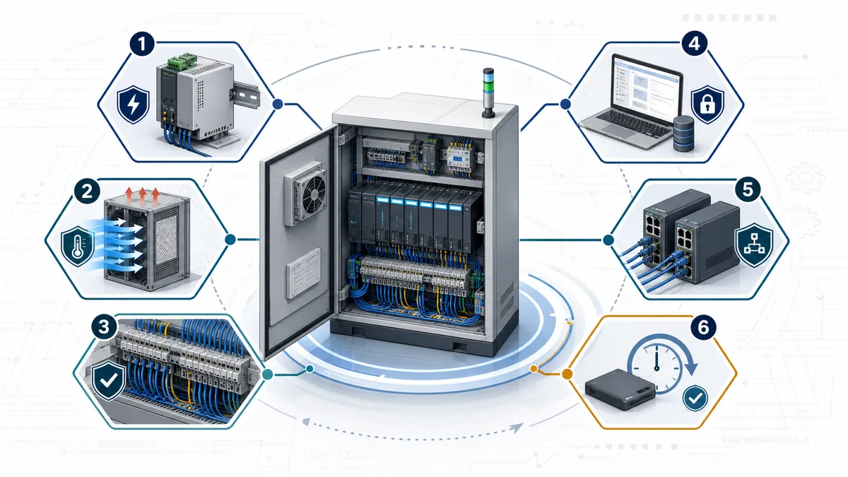
Build the maintenance plan from failure modes and consequence
Generic task lists tend to grow without showing which risk each task controls. Start instead with the function the automation system must preserve, the credible ways that function can be lost and the consequence of delayed recovery. This changes a ritual such as “check PLC annually” into a testable task such as “inspect the cabinet cooling path for blockage and record abnormal temperature evidence before the known high-ambient season.”
ISO 55001:2024 frames asset management around achieving objectives while balancing performance, risk and expenditure over the lifecycle. A PLC maintenance plan applies that idea at system level. It should spend the most effort where failure consequence, likelihood, detectability, recovery time and uncertainty justify it—not simply where a checklist has the most rows.
Define the protected function and acceptable recovery
For each PLC-controlled asset, record the production or utility function, safety and environmental interfaces, maximum tolerable outage, quality impact, restart constraints and required proof before release. A controller failure on a convenience conveyor is not the same business problem as losing a water-treatment interlock, cold-storage compressor sequence or batch genealogy path.
Define recovery objectives in operational terms. “Back up the PLC” is not an outcome. “A competent technician can install the approved spare CPU, load the released automation package, re-establish communications, prove required functions and hand the asset back within the agreed outage while preserving safety and quality evidence” is closer. It exposes missing tools, credentials, device files and test steps.
Build a PLC failure-mode register
Keep the register specific enough to drive work. “PLC failure” hides very different mechanisms: incoming supply disturbance, control-power overload, overheating, connector fretting, moisture, a failed storage device, a network loop, incompatible firmware, an unauthorized edit, lost HMI source, corrupt parameters or an obsolete part with no compatible replacement.
| Failure mode | Early evidence | Preventive or readiness control | Recovery evidence |
|---|---|---|---|
| blocked airflow or failed fan | temperature trend, fan alarm, visible contamination, abnormal noise | inspect exact cooling path; replace/clean only as the manufacturer permits | post-work temperature and alarm status under representative load |
| unstable 24 VDC distribution | power-supply diagnostics, undervoltage events, resets across multiple nodes | inspect loading/distribution and investigate common-cause events with authorized test methods | stable supply, event-free monitored run and cause recorded |
| loose, damaged or contaminated connection | intermittent channel, heat/discoloration, corrosion, motion-related fault | risk-based visual inspection and manufacturer-approved connection work under safe conditions | channel/network stability and inspection record |
| controller/storage loss | battery/storage diagnostic where applicable, media error, aging asset | complete verified backup, compatible spare and rehearsed restore | checksums, baseline identity and successful functional proof |
| unauthorized or undocumented change | signature/hash mismatch, unexplained timestamp or logic difference | access control, change approval, versioned release and periodic comparison | approved change record and released baseline |
| firmware/tool mismatch | device recognized incorrectly, download refusal, changed behavior after replacement | compatibility matrix, installer/archive retention, staged update process | recorded versions and acceptance/regression results |
| network degradation or topology error | port errors, duplicate address, connection timeout, intermittent I/O | managed topology, configuration backups, diagnostics baseline and controlled replacements | normal connections, error counters and communications proof |
| lifecycle/obsolescence gap | manufacturer status change, long lead time, unsupported OS/tool | quarterly or risk-triggered lifecycle review, tested spares, migration roadmap | successful spare test or approved migration package |
Rank consequence, detectability and restoration uncertainty
Do not use a single “critical PLC” label. Separate at least five questions: what happens if it fails; how likely the failure mode is in the real environment; whether deterioration can be detected before loss of function; how long diagnosis and restoration take; and how confident the team is that its backup, spare and procedure work.
A low-failure-rate device can still deserve priority when restoration is uncertain. Conversely, a module with occasional failures may be manageable when diagnostics are clear, a verified spare is nearby and replacement is routinely rehearsed. This is why manufacturer MTBF figures or generic internet failure rates cannot select the maintenance plan by themselves.
Assign every task an owner and acceptance condition
Every recurring task needs a competent role, safe-work prerequisite, trigger or interval, required tools, model-specific instruction, evidence to capture, pass/fail criterion and escalation path. “Clean cabinet” is incomplete. It does not say whether power must be isolated, which material and method are permitted, how electrostatic discharge is controlled, what contamination requires engineering review or how correct airflow is proved afterward.
Establish a trusted baseline before optimizing maintenance
You cannot recognize drift if the intended state is unknown. Create one approved baseline for each recoverable automation system and make the physical asset traceable to it. The baseline is more than the latest controller file; it is the information needed to understand, rebuild and validate the installed system.
Record the installed hardware and identity
Capture controller family and exact catalog number, chassis/rack and slot layout, module revisions, network adapters, removable media, industrial switches, HMI panels, drives, remote I/O, safety components, specialist gateways and any licensed or keyed devices. Record serial numbers where they improve traceability, but do not expose sensitive identifiers publicly.
Photographs can support the record if policy permits, especially for module order, switch settings, connector placement and cabinet condition. They do not replace drawings or configuration exports. Date them and link them to the asset and approved work order so a future technician can tell what they represent.
Record software, firmware and engineering dependencies
List the controller firmware, engineering application and major version, required device profiles or description files, libraries, safety packages, add-on instructions, communication configurators, HMI software, drive tools, licenses and supported workstation/operating-system dependencies. Retain installers and entitlements according to vendor license terms and organizational policy.
Rockwell’s March 2025 ControlLogix 5580 and GuardLogix 5580 user manual, for example, requires attention to controller firmware and Studio 5000 Logix Designer major-version compatibility. That is a product-family example, not a universal version rule. Siemens, Schneider, Beckhoff, Omron and other ecosystems have their own matrices and procedures.
Record the operational baseline
Store normal controller status, task or scan behavior, memory use, connection status, network topology, managed-switch configuration and relevant port-error baselines. Capture normal process evidence such as representative cycle time or sequence state only when it is meaningful and governed. A baseline should help distinguish a new symptom from a long-standing characteristic; it should not become an uncontrolled collection of sensitive plant data.
| Baseline layer | Minimum useful record | Verification question |
|---|---|---|
| physical | exact components, revisions, layout, wiring/drawing revision | does the record match the cabinet and network now? |
| controller | editable source, compiled/download identity where applicable, hardware tree and parameters | can the released project be opened and compared with the installed state? |
| connected assets | HMI, drive, robot, remote I/O, switch and gateway files | would controller recovery leave another device as the missing dependency? |
| tools | supported engineering versions, profiles, libraries, installers and licenses | can an approved workstation actually perform the restore? |
| security | roles, credential escrow, certificates/keys, secure storage and access audit | can an authorized responder recover without shared uncontrolled credentials? |
| validation | test plan, expected behavior, safety/quality hold points and sign-off roles | how will the team prove the restored machine is ready? |
Inspect the PLC cabinet without creating a new failure
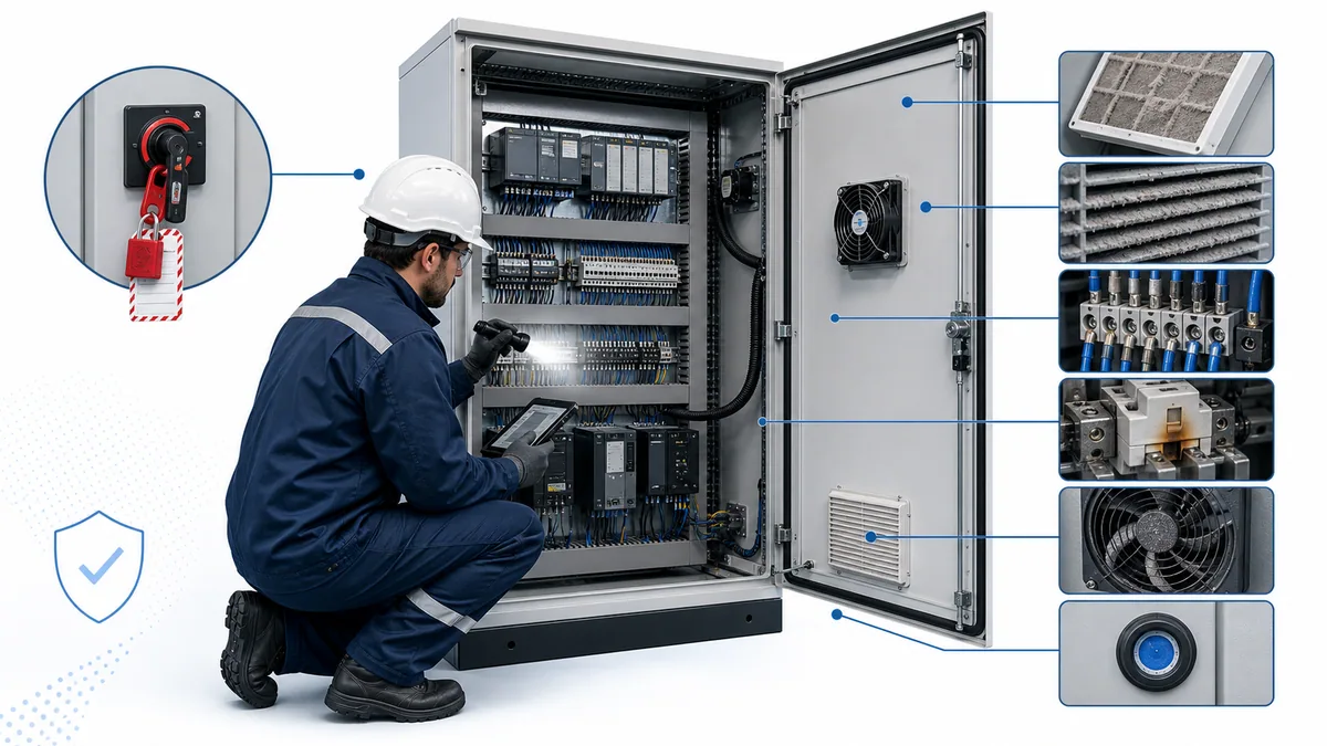
Electronics maintenance is often an inspection and environment-control discipline, not aggressive cleaning or routine disturbance. Rockwell’s preventive-maintenance checklist advises periodic visual inspection for solid-state equipment, checking that circuit boards and locking tabs are seated, cleaning or replacing filters according to environmental conditions, using factory-recommended test equipment and keeping maintenance records and parameter settings. It also warns against solvents on printed circuit boards.
Apply only the instructions for the exact installed equipment. A drive checklist can inform a system-level program, but it is not permission to service a PLC, power supply or network switch in the same way. Component materials, cooling paths, coating, connector mechanics and electrostatic-discharge requirements vary.
Observe before disturbing
When safe and permitted, capture status diagnostics and symptoms before cycling power, reseating hardware or clearing faults. A reset can erase the first-out condition and make an intermittent common-cause fault look like unrelated module failures. Record which devices lost communications, which indicators changed first, what the process was doing and whether recent work or environmental events correlate.
During an authorized inspection, look for dust mats, blocked filters, damaged fan guards, oil film, moisture tracks, corrosion, insect ingress, degraded seals, loose cable support, conductor damage, connector movement, discoloration, odor, unusual sound and unauthorized additions. Escalate signs of overheating or contamination; do not normalize them with a quick wipe and close the work order.
Protect airflow and thermal margin
Confirm that enclosure cooling, clearance, ventilation direction and filter media match the design and exact manuals. Replacing a filter with the wrong density can reduce airflow; leaving a cabinet door open can defeat the designed cooling and contamination boundary; adding an unmanaged heat source can remove margin without changing room temperature.
Trend cabinet or device temperature where it changes a decision, using installed diagnostics or an authorized measurement method. Treat a single spot reading carefully. Load, ambient, door state and measurement location affect it. The meaningful question is whether the equipment remains within its specified conditions with adequate margin under representative operation.
Use approved cleaning and connection methods
Do not spray solvents onto printed circuit boards. Do not assume compressed air is acceptable: it can drive conductive contamination deeper, overspeed fans, create electrostatic risk or violate the manufacturer’s method. If an exact manual permits air, vacuuming, brushing, filter washing or another method, follow its pressure, material, isolation and ESD controls.
Do not routinely tighten every terminal “just in case.” Connection maintenance must follow the component manufacturer, connection technology, conductor type, torque specification and site procedure. Unnecessary disturbance and over-torque can create damage. Thermal evidence, visual condition, maintenance history and exact instructions should drive the job.
Treat electrical measurements as planned work
Voltage, current, ripple, thermal and insulation tests can be valuable when they answer a defined question. They also introduce exposure and can damage electronics if applied incorrectly. Use competent authorized personnel, rated equipment, correct reference points and the site electrical-safety process. Never apply an insulation-resistance test through connected PLC electronics unless the manufacturer’s procedure explicitly defines it.
Use a risk-based PLC maintenance checklist
A checklist is a memory aid and evidence structure, not a universal schedule. Convert the following master questions into site job plans. Remove tasks that do not apply, add model-specific tasks, and set triggers from manuals, environment, criticality and observed degradation.
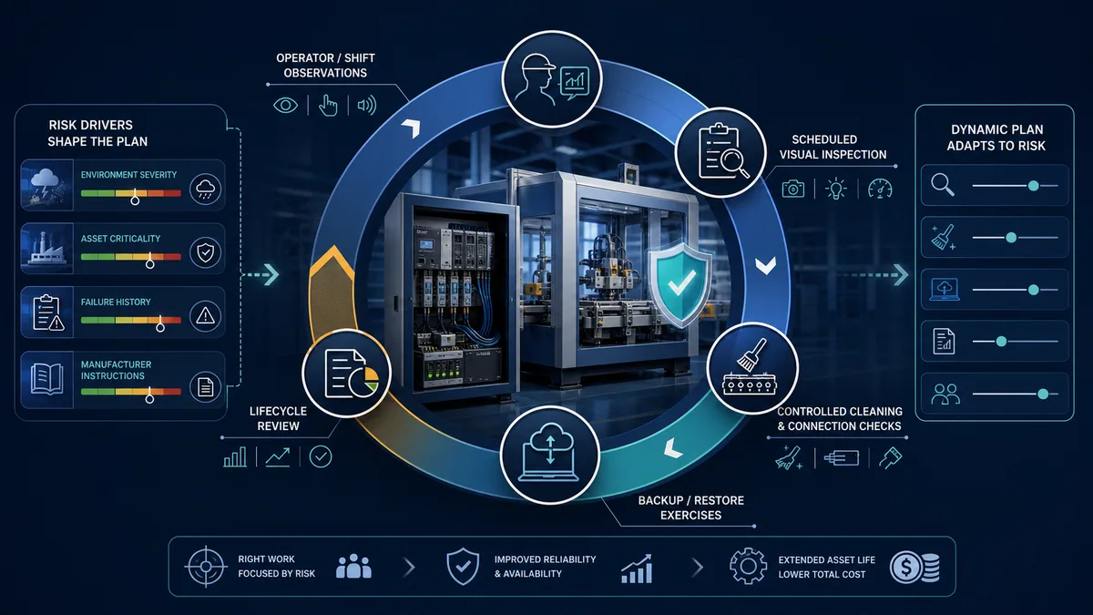
Operator and shift observations
Operators often see deterioration first: a cabinet cooler running continuously, an intermittent restart, a new network alarm, longer cycle time or a fault that appears after washdown. Give them a short route to record the time, machine state and exact symptom without opening an electrical enclosure or attempting a bypass.
Planned inspection and diagnostic review
Review controller, I/O, power-supply and network diagnostics that have a documented meaning. Inspect environmental controls and physical condition under the authorized work method. Compare findings with the prior record. A repeated “no defects” checkbox with no condition detail is weaker than a simple trend showing filter loading, temperature margin and recurring transient faults.
Backup, restore and toolchain exercise
Create or verify the automation package after approved changes and at a risk-based cadence. Prove that an authorized clean workstation can open it, required profiles and libraries resolve, checksums match and the restore procedure works on a representative spare, test rack or controlled exercise. Avoid downloading to production merely to test the backup.
Lifecycle, spares and support review
Check manufacturer lifecycle status, support entitlement, known compatibility constraints, repair options, lead times, installed-base count and migration dependencies. Review after major vendor announcements, operating-system changes, workstation replacement, facility projects and repeated failures—not only on a fixed date.
| Checklist area | Ask and record | Escalate when |
|---|---|---|
| environment | contamination, moisture, temperature evidence, airflow path, filter/fan/seal condition | conditions approach limits, degradation accelerates or contamination is conductive/corrosive |
| power | supply diagnostics, unexplained resets, common timing across devices, distribution condition | multiple nodes reset together, capacity/margin is uncertain or damage is visible |
| hardware/I/O | status, module seating/locking where the manual calls for it, physical damage, channel history | intermittent faults recur, revision compatibility is unknown or replacement changes configuration |
| network | connection state, port errors, topology/configuration baseline, time synchronization where relevant | errors trend upward, duplicate/loop behavior appears or an unmanaged change is found |
| software | project comparison, signatures/checksums, change records, task/connection anomalies | installed state differs from released baseline without an approved explanation |
| backup/toolchain | complete package, successful open/compile where appropriate, restore test, protected access | source is missing, versions do not resolve, restore has never been proven or credentials are unavailable |
| lifecycle/spares | vendor status, tested spare, repair/lead time, storage condition, migration roadmap | a critical component is end-of-life/discontinued or the spare is untested/incompatible |
| return to service | fault corrected, baseline comparison, safety and quality gates, monitored handoff | cause remains unknown, safeguards are not proven or new alarms appear |
Live mini-lab
Try it: press START, then STOP
A stop-dominant seal-in rung: START latches the motor output through its own contact, and STOP breaks the circuit.
Watch the output lamp: it stays on after START until you press STOP.
Free · no signup to try · runs in your browserOpens plcsimulationsoftware.com — same team
Build a PLC backup that can actually restore the machine
An upload is not automatically a source backup, and a controller project is not automatically a machine recovery package. Uploaded logic may omit comments, symbols, libraries, version history, HMI source, drive parameters or external configuration. Some platforms store important data outside the CPU; some backup methods change operating state; some require matching firmware or engineering tools.
NIST SP 1339, OT Backup Quick Start Guide, published in June 2026, recommends integrating OT backups into change management, creating them regularly, testing them and reviewing them during recovery exercises. NIST SP 800-82 Revision 3 places OT cybersecurity controls within performance, reliability and safety constraints. Together they support a practical principle: protect automation backups as controlled operational assets, then prove recovery under conditions that respect the process.
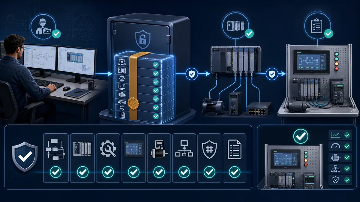
Minimum contents of a golden automation package
The exact package varies, but the recovery review should deliberately accept or reject each layer rather than assume the CPU contains everything.
| Package component | Why it matters | Verification evidence |
|---|---|---|
| editable controller source | supports review, comparison, troubleshooting and controlled modification | opens in the approved tool; hardware tree and symbols resolve; release identity recorded |
| compiled/download artifact or signature where applicable | ties the approved source to what executes | vendor-supported comparison, signature, checksum or release record |
| hardware and I/O configuration | replacement devices may need slot, address, keying and connection settings | exact catalog/revision assumptions and tested replacement path |
| firmware and engineering-tool matrix | an otherwise healthy spare may reject or alter the project | supported combinations, retained installers/profiles and staged proof |
| HMI/SCADA source | operator control and alarm context may be essential to restart | source opens; target/runtime version and communications are known |
| drive, motion, robot and intelligent-device parameters | controller logic may reference behavior stored in another device | exports captured and restoration method tested or vendor-verified |
| switch, gateway and network configuration | topology, VLAN, address and protocol settings can block I/O | versioned export and approved recovery access |
| recipes, calibration and retained data | production may depend on values not present in logic | ownership, export method, sensitivity and validation defined |
| credentials, certificates, keys and licenses | authorized recovery may fail without protected access material | secure escrow, access audit and expiry/replacement process |
| drawings, addresses and restore instructions | responders need context and safe sequencing | field-checked revision and stepwise rehearsal record |
| acceptance test and expected results | a successful download does not prove operation | safety, quality and functional gates with named approvers |
Distinguish source, upload, image and runtime backup
A native source project retains engineering intent and is usually the preferred master. An upload is a readback from installed equipment; what it contains depends on the platform and how the original was downloaded. A storage image may clone a device or medium but be less reviewable. A runtime backup may support fast replacement without containing editable source. Record which artifact you have and what it cannot reconstruct.
The November 2024 Siemens S7-1500 and ET 200MP system manual documents multiple backup and restore paths with different contents and operating-state implications; some actions require or trigger CPU STOP. That is exactly why “take a backup online” is not a platform-neutral instruction.
Verify integrity, identity and access
Store a manifest with asset ID, approved release, creator/reviewer, timestamps, source path, tool/firmware versions and cryptographic checksums where policy allows. Protect backups from unauthorized modification and ransomware, maintain appropriate offline or isolated copies, and test that authorized responders can retrieve them. Encryption without recoverable keys and an inaccessible administrator account are both availability failures.
Use role-based access and an audit trail rather than a shared engineering password. Preserve credentials and certificates through an approved escrow process. Do not embed secrets in a public restore document or unencrypted project note.
Test restoration without gambling with production
A strong restore exercise proves the package on a compatible spare, test rack, digital lab or planned recovery environment. It verifies that the project opens, dependencies resolve, hardware can be configured, device identities can be established and acceptance tests are executable. A simulator can help rehearse diagnosis and logic expectations, but it does not prove real I/O, field wiring, network timing, firmware behavior, safety response or machine mechanics.
If the organization must test on production, treat it as a controlled change with outage authorization, complete backup, rollback decision points, hazardous-energy controls, safety/quality hold points and competent supervision. Never download or power-cycle a running process merely to satisfy a generic backup checkbox.
Control firmware, software and security changes as maintenance
Firmware maintenance is a compatibility and operational-risk decision, not a race to install the largest version number. A release may correct a defect or security weakness, add hardware support or satisfy a vendor recommendation. It can also change communications, module profiles, retained data, instruction behavior, certificates or the engineering tool needed for future support. Decide from the exact release notes, affected asset, exposure, compensating controls and a tested implementation plan.
Build a compatibility matrix before touching the asset
Record the current and proposed controller firmware, engineering-tool version, I/O and communication-module revisions, device profiles, HMI runtime, drive firmware, safety components, libraries and operating-system support. Identify whether an intermediate upgrade is required and whether a downgrade is supported. Confirm the procedure in the current manual and vendor compatibility resources rather than relying on a forum recipe for a similar product.
Rockwell directs users of its current controller platforms to product compatibility information and matching engineering versions. Schneider’s May 2025 Modicon M580 firmware installation guide contains family- and version-dependent procedures. These examples reinforce the same boundary: a generic article cannot tell an engineer which file to flash or whether a live process can tolerate the required mode change.
| Change-control gate | Required answer before approval | Evidence after execution |
|---|---|---|
| reason | which defect, risk, support requirement or capability justifies the change? | approved request tied to release notes/advisory |
| compatibility | which hardware, firmware, profiles, libraries and tools must coexist? | recorded as-built version matrix |
| operating impact | will the controller, I/O, network or process stop or reinitialize? | event chronology and actual outage record |
| backup/rollback | what complete backup exists, and is downgrade or replacement supported? | verified backup identity and rollback disposition |
| test | which lab, staging and production acceptance cases prove no regression? | signed results, deviations and residual risk |
| security | how is the authentic file acquired, verified, protected and audited? | source, integrity evidence and access log |
| handoff | who releases the system, and what monitoring follows? | release approval and stable monitored window |
Stage, back up and define rollback limits
Acquire firmware through the vendor’s authorized channel, verify integrity by the supported method and keep the release notes with the job package. Test the exact or representative hardware combination where practical. Before the change, preserve the complete automation baseline and decide the rollback path. Some products do not support a simple downgrade, and a firmware change may convert a project or invalidate a safety signature.
Set explicit hold points: power preconditions, process state, redundant-partner state where applicable, controller mode, network availability and physical access. Include what to do if the tool loses connection, the device remains in boot mode, the replacement has a different revision or an external module does not reconnect.
Validate behavior, not just version display
After the update, confirm hardware/module health, communications, time synchronization where used, application comparison or signature, retained values, alarms, recipes, motion/drive interfaces and representative sequence behavior. Revalidate affected safety and quality functions under the governing process. A version screen showing the expected number proves identity; it does not prove the machine.
Integrate cybersecurity without ignoring availability
OT maintenance and cybersecurity are one change system. NIST SP 800-82 Revision 3 explicitly recognizes OT performance, reliability and safety requirements. Use risk assessment, segmentation and access control to reduce exposure while a patch is evaluated, but do not leave an undocumented permanent exception. Likewise, do not force an update into an unsafe operating window merely because IT cadence says “patch Tuesday.”
Handle batteries, memory and retained data by exact controller model
“Replace the PLC battery every year” is not a valid universal task. Some legacy controllers use a replaceable battery to retain memory or clock data. Some newer controllers use nonvolatile memory, a capacitor/energy-storage module, removable storage or a combination. Some batteries can be replaced with the controller powered under a tightly defined procedure; other actions would create unacceptable exposure or data loss. The catalog number, hardware revision and manual decide.
Inventory the actual retention mechanism
For each controller, record whether it has a user-serviceable battery, what the battery supports, diagnostic bits or indicators, replacement part, storage life, replacement conditions and the consequence of total energy loss. Inspect the installed unit; do not infer the answer from another CPU in the same family.
Back up before responding to a battery alarm
A battery alarm is a maintenance trigger, not permission to open a live cabinet. First preserve the recoverable application and retained values by an authorized method. Then plan the work under the exact manufacturer and site procedure. If a powered replacement is suggested by old tribal knowledge, stop and verify whether energized work is allowed and justified under current rules.
Treat retained values as configuration data
Recipes, totalizers, calibration factors, learned positions and operator settings may be more important to restart than the ladder logic. Classify which values are source-controlled, which are commissioned, which change during operation and which contain sensitive or regulated data. Define a sanctioned capture and validation method; blindly restoring stale retained data can be as harmful as losing it.
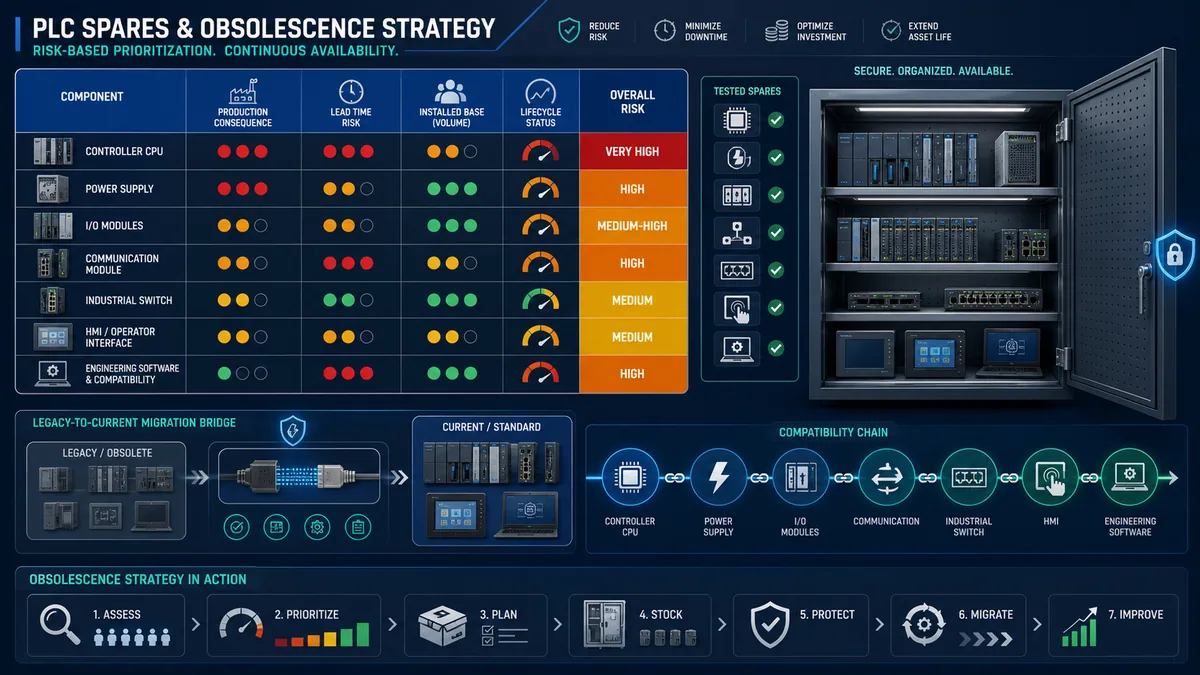
Design spares and obsolescence around compatible recovery
A spare part has value only if it is authentic, stored correctly, compatible with the approved baseline and usable by the available team and tools. A sealed CPU on a shelf can still fail the recovery test because its firmware is wrong, its memory is blank, a license is missing, its battery aged in storage or the project needs an unavailable engineering workstation.
Rockwell’s product lifecycle definitions distinguish Active, Active Mature, End of Life and Discontinued states. Other manufacturers use different labels. Track the supplier’s current status and last-order/repair dates for the exact catalog item; never convert one vendor’s label into a universal rule.
Prioritize the recovery bottleneck
Build a bill of material across the whole control path. The bottleneck may be a power supply, network adapter, remote-I/O coupler, proprietary gateway, HMI panel, industrial PC, drive option card or software license rather than the CPU. Consider common-cause exposure: ten machines using one obsolete network module can justify a strategy even when each machine is individually low criticality.
| Spares factor | Question | Practical decision |
|---|---|---|
| production consequence | what safe, environmental, quality and output loss follows failure? | sets urgency and recovery objective |
| installed-base count | how many assets depend on the exact part or compatible family? | supports pooled spares and migration leverage |
| diagnostic certainty | can the failed module be identified without swapping parts blindly? | determines test equipment and training need |
| lead/repair time | how long to acquire an authentic replacement or repair? | sizes local stock or service agreement |
| compatibility | which revisions, firmware, keys and profiles are accepted? | defines tested replacement matrix |
| storage degradation | do batteries, capacitors, media, seals or contacts age on the shelf? | defines inspection, rotation and environmental storage |
| lifecycle status | when do standard support, last-time buy and repair end? | triggers migration business case |
| migration complexity | which code, I/O, networks, drawings, validation and skills change? | prevents a last-time buy from becoming the only plan |
Test and rotate critical spares
On receipt, verify source, catalog number, revision, physical condition and storage requirements. Where risk justifies it, test the spare on a representative bench and record firmware, configuration and proof. Maintain anti-static, temperature, humidity, packaging and battery conditions specified by the manufacturer. Periodically re-evaluate whether the test itself could consume limited service life or disturb a configured spare.
Do not keep an unlicensed “emergency” engineering laptop as the whole plan. Maintain a sanctioned workstation image or build procedure, supported tools, offline installers where permitted, device profiles, cables/adapters and access material. Prove that the workstation can connect in a controlled environment without weakening network security.
Plan migration before the last spare becomes a crisis
A lifecycle plan should compare continued support, repair, last-time purchase, stocked spares and engineered migration. Rockwell’s legacy product support illustrates vendor options such as migration, repair and last-time buys; exact availability changes by product and region.
Migration scope includes source conversion, instruction behavior, I/O electrical compatibility, network architecture, HMI and drive interfaces, safety validation, cybersecurity, drawings, training, acceptance testing and rollback. Use scheduled plant work to remove the highest uncertainty first: build a test rack, convert one representative machine or qualify a gateway before support disappears.
Diagnose PLC failures from evidence, not replacement guesses
The fastest sustainable troubleshooting sequence preserves the first symptom and tests boundaries. It does not begin by downloading the “latest” program, reseating every module or replacing the CPU. Many apparent PLC failures are power, field-device, wiring, network, configuration or process problems.
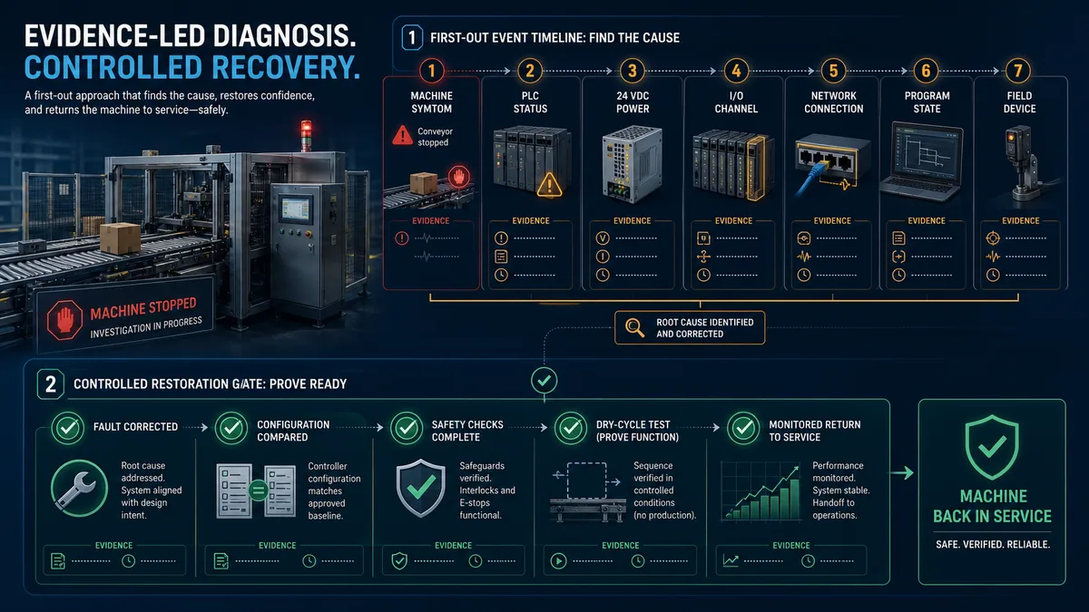
Capture the first-out timeline
Record when the machine symptom appeared, which alarms and controller/module indicators were present, which nodes disappeared together, whether power or network events preceded it and what changed recently. Keep clocks synchronized where the architecture supports it, but understand their accuracy. An HMI, PLC and switch may timestamp the same event differently.
Divide the system at observable boundaries
Check the safest high-information boundaries in an order suited to the asset: incoming/control power, controller state, rack/module state, network connections, physical input evidence, program permissives/state, output command, output module/channel, field power and final device. Do not force outputs or defeat interlocks to “see what happens.” Use documented status and authorized tests.
| Symptom pattern | High-value evidence | Avoid the premature conclusion |
|---|---|---|
| several remote nodes drop at once | common 24 VDC supply, switch/uplink, adapter and controller connection history | multiple I/O modules failed simultaneously |
| one input flickers with machine motion | field-device indication, connector/cable path, input diagnostics and timestamp | PLC scan is too slow |
| CPU returns to run but sequence will not start | first unmet permissive, mode, reset/restart state, retained data and device readiness | program must be re-downloaded |
| fault follows recent replacement | catalog/revision, firmware, electronic keying, address, parameters and wiring | replacement is defective |
| intermittent reset during load change | power event, common supply loading, contactor/solenoid suppression and grounding evidence | random software bug |
| communication degrades gradually | port errors, physical media, topology, load, multicast/broadcast behavior and environmental correlation | network needs a faster switch |
Preserve evidence before reset or replacement
Take screenshots or exports according to policy, note status words and module diagnostics, and save relevant event logs before clearing them. Mark swapped parts and preserve their original positions. A successful restart after replacement does not prove the removed part was causal; the power cycle, connector disturbance or cleared state may have changed the symptom.
Correct the cause and update the maintenance system
Close the loop from fault to task design. If a blocked filter caused overheating, determine why the plan missed it: wrong interval, wrong media, unexpected environment or poor inspection evidence. If restoration was delayed by missing software, correct the backup/toolchain control. If a connector failed after repeated disturbance, revise the work method. A good corrective action reduces recurrence or restoration uncertainty, not just the open work-order count.
Practise the evidence sequence in the PLC troubleshooting simulator before using it on production. A browser lab can teach symptom capture, boundary testing and repair verification; it cannot authorize real electrical work, reproduce every vendor diagnostic or validate installed safety and process behavior.
Return the machine to service through controlled gates
Maintenance is not complete when a fault disappears. The system must be returned in a known configuration, with safeguards and affected functions proven, temporary controls removed, production acceptance recorded and follow-up monitoring assigned.
Gate 1: confirm the cause and correction
State the evidence that identifies the cause, the correction made and why it addresses the failure mode. If the cause remains uncertain, record the uncertainty and residual risk. Do not write “PLC fault—reset” when the evidence only shows that a reset temporarily restored operation.
Gate 2: compare with the approved baseline
Confirm hardware/revision, wiring and configuration changes; compare controller and connected-device projects using vendor-supported methods; record firmware and tool versions; remove forces and temporary test logic; reconcile drawings and the change record. An upload made after an uncontrolled edit should not silently become the new master.
Gate 3: prove safety, quality and functional behavior
Follow the machine-specific acceptance plan. Verify affected protective functions and safe states under the competent safety process, confirm calibration/quality controls, perform static or dry-cycle checks where appropriate and then run representative operation. The scope should match the change and the possibility of common effects; replacing a network switch may affect more assets than the initial failed signal suggests.
Gate 4: monitor and hand off
Define a monitored period with owners and stop criteria. Review diagnostics, alarms, temperature, communication errors, cycle behavior and recurring symptoms that relate to the event. Tell operations what changed, what to watch and how to escalate. Update the maintenance plan, spares status, backup and lessons learned before closing the job.
Redundancy is not a backup
High-availability controllers can reduce interruption from some hardware failures. Schneider’s Modicon M580 Hot Standby system guide describes a system based on identically configured controllers. A synchronized partner can also receive a bad configuration, logic error or harmful command. Redundancy does not preserve an independent historical baseline, engineering toolchain or recovery procedure. Use both where risk warrants: redundancy for continuity, backups for reconstruction.
Measure reliability without gaming the numbers
Use metrics to expose risk and learning, not to reward deferred work. MTBF and MTTR are estimates derived from a defined population and observation method; they are not universal characteristics of “a PLC.” Define whether downtime starts at process loss, alarm, work notification or technician arrival, and whether it ends at first motion, stable production or quality release.
Combine lagging and readiness measures
| Measure | Useful definition | What it reveals | Common distortion |
|---|---|---|---|
| automation-attributable interruption hours | lost operational time with evidence assigning the automation boundary | consequence trend and repeat mechanisms | blaming every electrical/process stop on PLCs |
| mean diagnosis time | symptom recognition to evidence-supported cause | diagnostic quality and observability | ending the clock at a reset without a cause |
| mean restoration time | approved repair start to validated service | procedure, spares and test readiness | ending at CPU RUN before machine acceptance |
| repeat-fault rate | same mechanism/asset recurs inside a defined window | quality of corrective action | changing descriptions to hide recurrence |
| verified-backup coverage | critical assets with complete, current package and successful restore evidence | recoverability | counting untested controller uploads |
| compatible-spare coverage | critical recovery paths with tested/authentic compatible replacement | supply and lifecycle exposure | counting parts without firmware/tool proof |
| unauthorized-baseline drift | installed systems differing from released configuration without approval | change-control health | automatically promoting drift to baseline |
| overdue risk actions | unresolved high-risk environment, lifecycle or recovery gaps | forward-looking exposure | closing actions without evidence |
Keep reliability data contextual
Record asset, operating hours/cycles where meaningful, environment, symptom, failed boundary, cause confidence, correction, parts, versions, downtime phases and validation. Compare like with like. A change in reporting discipline can look like a reliability decline even when technical performance improves.
Review the control, not only the device
When a KPI worsens, ask whether detection, escalation, documentation, tooling, spare compatibility or acceptance tests contributed. A two-minute module replacement after four hours finding the right project is a configuration-management problem. A recurring input fault after every washdown is an environment or installation problem. The metric should route work to the controlling system.
Worked example: intermittent conveyor PLC recovery
Consider a case conveyor that stops several times per week. The HMI displays “remote I/O unavailable,” but the alarm disappears after a cabinet power cycle. Prior work orders call it an intermittent PLC fault and show two replaced I/O modules.
Preserve the timeline
The team changes the response. Operators record the time and operating state without opening the enclosure. An authorized technician captures controller connection diagnostics, managed-switch port history and 24 VDC power-supply status before reset. Three remote devices lose connection within the same second, while the local PLC remains in run. The common timing makes three independent I/O failures unlikely.
Test the shared boundaries
The topology record shows the affected nodes share one cabinet switch and power branch. Under a planned safe inspection, the technician finds a heavily loaded filter and heat discoloration near the branch power-supply connector. Engineering reviews the rated environment, loading and connection method using the exact manuals. The approved work corrects the damaged connection, restores cooling and confirms supply margin.
Restore and validate
No program is downloaded because comparison shows that the installed controller matches the approved baseline. The team proves network connections and I/O status, completes required safeguard checks, dry-cycles the conveyor and monitors it under representative load. Port errors and device-loss events remain normal through the handoff window.
Improve the maintenance system
The corrective action is not “replace power supply annually.” The site shortens the environment-inspection trigger for this dusty line, adds a recorded filter-condition criterion, updates the network/power first-out capture, checks similar cabinets and verifies the spare power supply plus connection hardware. The backup exercise also finds that the switch configuration had not been included, so it is added to the golden package.
This example illustrates the difference between restarting and improving reliability. Evidence identified a shared boundary; restoration proved the machine; maintenance controls were changed at the mechanism that allowed recurrence.
A 90-day implementation sequence
Do not wait for a perfect enterprise program. Start with the assets whose outage and recovery uncertainty create the greatest exposure, then build repeatable evidence.
Days 1–30: establish ownership and triage exposure
Name an operations owner, maintenance owner and controls/configuration owner. Select a small critical asset set. Record the protected function, maximum tolerable outage, hardware/software identity, current backup state, lifecycle status, safe-work procedure and recent failure history. Mark unknown restore capability as a risk rather than assuming it exists.
Days 31–60: build and verify recovery packages
Create the complete package for each selected asset, reconcile it with the installed baseline and protect it in the approved repository. Resolve missing tool versions, licenses, credentials and connected-device configurations. Perform a safe open/compare exercise and at least one representative restore rehearsal. Record limitations honestly.
Days 61–90: convert failure modes into job plans
Use environment and incident evidence to write model-specific inspections. Rank spare and obsolescence gaps. Train operators on symptom capture and technicians on first-out evidence. Establish controlled return-to-service gates and a short metrics review. Expand only after the first assets have real proof.
| Deliverable | Minimum acceptance condition | Owner |
|---|---|---|
| asset recovery objective | downtime consequence and validated-return definition agreed | operations + engineering |
| installed baseline | hardware, software, versions and connected assets field-checked | controls/configuration owner |
| golden package | complete manifest, integrity/access proof and representative restore evidence | controls + cybersecurity/IT as applicable |
| maintenance job plan | exact manual, safe prerequisites, criterion, evidence and escalation included | maintenance engineering |
| spares/lifecycle register | compatibility and vendor lifecycle evidence, not quantity alone | maintenance + procurement + controls |
| first-out workflow | operators and technicians can capture evidence without bypass/reset shortcuts | operations + maintenance |
| return-to-service plan | configuration, safety, quality, function and monitoring gates named | responsible asset owner |
Common PLC maintenance mistakes
| Mistake | Why it fails | Better control |
|---|---|---|
| copying a universal annual checklist | ignores environment, manuals and consequence | risk-based model-specific job plans |
| using compressed air by default | can spread contamination, damage fans or create ESD risk | exact manufacturer-approved cleaning method |
| replacing “the PLC battery” on every controller | retention designs and procedures vary | inventory the exact retention mechanism and manual |
| calling an upload a complete backup | may omit source context and connected-device files | manifest the full automation package and test restore |
| always installing latest firmware | ignores compatibility and operational impact | release-driven, staged change with rollback analysis |
| power-cycling before capturing status | destroys first-out evidence | capture timeline and boundary diagnostics first |
| swapping modules until the fault clears | disturbs connectors/state and weakens cause confidence | test shared boundaries and preserve removed-part evidence |
| treating a redundant partner as backup | duplicates bad logic/configuration and lacks historical source | independent protected baseline plus restore exercises |
| keeping untested legacy spares | storage aging and compatibility remain unknown | authentic, protected, tested spare strategy |
| returning service at CPU RUN | does not prove safeguards, I/O, process or quality | controlled acceptance and monitored handoff |
Frequently asked questions
What maintenance does a PLC need?
A PLC needs system-level maintenance: protect its specified environment and power, inspect cabinet and connection condition using exact manuals, review diagnostics, control software and firmware changes, maintain verified backups and compatible spares, manage obsolescence and prove restoration. The controller itself may require little routine physical intervention; aggressive cleaning or unnecessary reseating can create failures.
How often should PLC preventive maintenance be done?
There is no universal interval. Set task frequency from the exact manufacturer instructions, contamination and thermal severity, asset consequence, observed degradation, failure history, legal/site requirements and available outage windows. Operator observations may be continuous while invasive work occurs only when justified and safely planned.
What should be included in a PLC maintenance checklist?
Include environment and cooling, control power, controller/I/O status, network health, physical condition, baseline comparison, backup/toolchain readiness, connected-device configurations, spare compatibility, lifecycle status and controlled return-to-service evidence. Every row needs an owner, safe prerequisite, pass criterion and escalation path.
Is a PLC upload a complete backup?
Not necessarily. Upload contents vary by platform and may omit original comments, symbols, libraries, version history, HMI source, drive or robot parameters, switch configuration, recipes, licenses and restore instructions. Label the artifact accurately and maintain a manifest for the complete automation package.
How do I test a PLC backup without risking production?
Open and compare it on an authorized clean workstation, verify dependencies and integrity, then restore to a compatible spare, test rack or controlled recovery environment. Use a defined acceptance test. If production involvement is unavoidable, manage it as a planned change with outage, rollback, safety and quality gates.
Should PLC firmware always be updated to the latest version?
No. Evaluate the exact release, defect or security reason, vendor compatibility matrix, process impact and support state. Stage the change, verify the authentic file, preserve a complete backup, define rollback limits and test affected functions. “Latest” alone is not a maintenance justification.
How often should a PLC battery be replaced?
Only the exact controller manual can answer. Some controllers have a replaceable retention battery; others use nonvolatile memory, removable storage or another energy-storage design. Record the model, diagnostic indication, supported part, replacement conditions and data-loss risk, and back up before authorized work.
What are the most common causes of apparent PLC failure?
Common boundaries include unstable control power, cabinet heat or contamination, field-device and wiring faults, network problems, incompatible replacements, configuration drift, lost retained data and external devices such as HMIs or drives. Capture first-out evidence before deciding the CPU failed.
Is a redundant PLC the same as having a backup?
No. Redundancy can maintain operation through specified failures, but synchronized partners can share bad logic or configuration. A backup preserves an independent, controlled reconstruction package with source, versions, connected-device files and restore evidence. Critical systems may need both.
Can a PLC simulator validate a maintenance or recovery procedure?
No. Simulation can train symptom capture, program-state reasoning, boundary tests and repair verification. It cannot validate installed electrical energy controls, real I/O and wiring, firmware compatibility, network timing, safeguarding, mechanics or process quality. Use it as preparation, then follow the real manufacturer and site acceptance process.
Primary references and evidence boundary
The following direct sources support the general framework and the dated product examples. They do not make this page a substitute for the exact catalog-number manual, current release notes, adopted standards, machine risk assessment or site work procedure.
| Primary source | Evidence used here |
|---|---|
| ISO 55001:2024 asset management | performance, risk, expenditure and lifecycle framing |
| NIST SP 800-82 Revision 3 | OT security within performance, reliability and safety constraints |
| NIST SP 1339 OT Backup Quick Start Guide | integrate, create, test and exercise OT backups |
| OSHA 1910.147 Appendix A | typical hazardous-energy control procedure boundary |
| OSHA standard interpretation, 21 October 2024 | current United States interpretation context for energy-control work |
| NFPA 70B, 2026 edition page | current electrical equipment maintenance standard reference; access the applicable text |
| Rockwell DRIVES-TD001C-EN-P | visual inspection, filters, test equipment, records and no PCB solvents |
| Rockwell ControlLogix/GuardLogix 5580 user manual, March 2025 | controller/engineering major-version and firmware workflow example |
| Siemens S7-1500/ET 200MP system manual, November 2024 | backup/restore method contents and STOP-state implications |
| Siemens S7-1500 IEC 62443-4-2 conformity guidance, May 2025 | controller backup and integrity-verification examples |
| Schneider Modicon M580 firmware installation guide, May 2025 | product- and version-specific firmware procedures |
| Schneider Modicon M580 hardware guide, July 2026 | current family hardware and product-specific maintenance context |
| Schneider Modicon M580 Hot Standby guide, May 2025 | redundancy architecture and identical-configuration example |
| Rockwell product lifecycle status definitions | Active through Discontinued lifecycle terminology |
| Rockwell legacy product support | repair, last-time-buy and migration strategy examples |
Source and standards status checked 30 August 2026. Confirm revisions at the time of work. Manufacturer instructions and support status can change, and local law, contractual requirements and machine-specific standards can impose stricter controls.
Now run it · free · no signup
Run your first PLC program in your browser
Build one rung, press Run and watch the output change in a free browser lab. Nothing to install and no signup needed to try it.
Ownership disclosure: PLC Programming IO and PLC Simulation Software are operated by the same publisher.
PLC Programming IO Editorial Team
Industrial automation education, references, and software testing
The PLC Programming IO Editorial Team publishes sourced industrial-automation education and documents how material is reviewed, tested, and corrected. A team byline means the publisher is responsible for the page; it does not represent a fictional person or imply an engineering licence.
Coverage:
- • PLC programming concepts and examples
- • Vendor software tutorials and comparisons
- • SCADA, HMI, protocols, and instrumentation
- • Training, careers, and reference material
Review standard:
- • Prefer primary and official sources
- • Record software versions when material
- • Separate tested facts from estimates
- • Publish material corrections
Important scope note
This site provides education, not project-specific engineering approval. Safety, code, and compliance decisions require a qualified person with access to the actual machine and jurisdiction.