PLC Program Architecture, Testing and Code Quality: Practical Guide
Design PLC software for deterministic tests, apply review and static-analysis gates, automate unit and integration regression, and connect results to emulator, HIL, FAT and SAT evidence.
Review status: Editorially reviewed against current IEC 61131-3:2025 scope, PLCopen Coding Guidelines and Software Quality Metrics, current CODESYS Test Manager 5.1 documentation, Beckhoff TE1200 TwinCAT PLC Static Analysis 2.10.2 material, current Siemens TIA Portal Test Suite V21 and S7-PLCSIM Advanced V8 surfaces, current Rockwell FactoryTalk Logix Echo product material, ISA-88/ISA-95 context and current functional-safety lifecycle references; exact tool, compiler, library, emulator, target, task, I/O, motion, network, safety and physical process test behavior require project-specific verification
Direct answer
Good PLC program testing begins with architecture, not a test tool. Separate physical I/O mapping, signal qualification, reusable equipment behavior, sequence coordination and final output arbitration. Pass time, inputs and dependencies through explicit interfaces where the platform supports it. Then test small deterministic units quickly, multi-object behavior in integration, controller execution in simulation/emulation, real I/O and devices in HIL/FAT, and the installed process in SAT.
A compile is not a test; a simulator animation is not field validation; code coverage is not requirement coverage; and FAT does not replace unit regression. Use each gate for the faults it can reveal:
- review and static analysis for ownership, unsafe constructs, rule violations and maintainability;
- unit tests for functions, calculations, state transitions, priorities and boundaries;
- integration tests for object interactions, task order, handshakes, HMI and protocols;
- emulation for target/runtime behavior supported by the exact emulator;
- hardware tests for I/O, timing, networks, drives and real device diagnostics; and
- FAT/SAT for machine, process, operator, recovery and site requirements.
Every changed requirement should map to at least one positive, negative, boundary and recovery test as applicable. Record exact project hash, compiler/tool/library/firmware versions, initial state, stimuli, expected result, actual result, timing and first failure. Safety application validation remains a separate controlled lifecycle on the exact approved target.
Download the 24-case PLC test plan, 24-point code-review checklist and deterministic motor-object Structured Text example.
Turn requirements into testable contracts
Replace vague behavior with observable state
“Start the motor normally” cannot produce a decisive assertion. A testable contract states:
When
StartReqrises while Auto is selected, permissives are healthy, no fault is active and stopped feedback is proven, the motor object entersStarting, requests the run output, waits no longer than 30 task ticks for qualified running feedback, then entersRunning; otherwise it removes the command, latches the first applicable fault and requires an authorized healthy reset.
That sentence names initial state, trigger, guards, command, feedback, timeout, fault response and reset. Split it into requirement IDs and tests.
| Contract surface | Example | Test oracle |
|---|---|---|
| input/request | one rising StartReq with request ID if remote |
exactly one acceptance/rejection |
| permissive | Auto, overload healthy, no trip, process ready | start cannot leave Stopped when any required guard is false |
| state | Stopped → Starting → Running | only allowed transitions occur |
| command | RunCommand true in Starting/Running only |
output intent follows state and one owner |
| feedback | independent qualified RunFeedback |
command never substitutes for proof |
| timeout | 30 executions in deterministic harness; field time in target design | exact just-before/at/after boundary |
| fault | first-out code and latched Failed state | earliest cause retained; later symptoms do not overwrite |
| reset | fault clear, feedback stopped, conditions healthy, authorized edge | reset cannot restart automatically |
Create a trace matrix: requirement → design object → source revision → static rule/review → automated tests → integrated/FAT/SAT cases → release evidence. A single acceptance test may cover several requirements, but each requirement must still identify its decisive observation.
Include abnormal and simultaneous cases
At minimum consider:
- minimum, maximum, zero, invalid and overflow values;
- input transition just before/at/after a timer or count boundary;
- simultaneous Start/Stop, Set/Reset, fault/reset and mode changes;
- held versus pulsed requests;
- power, warm restart, download, task disable and re-enable;
- communication stale, bad quality, duplicated or reordered command;
- feedback that arrives late, disappears while running or contradicts command;
- array maximum, empty set and unexpected enumeration/state;
- first fault followed by secondary faults; and
- recovery that fails halfway and needs rollback.
Test priority deliberately. Accidentally passing one execution order is not a priority specification.
Architecture for testability
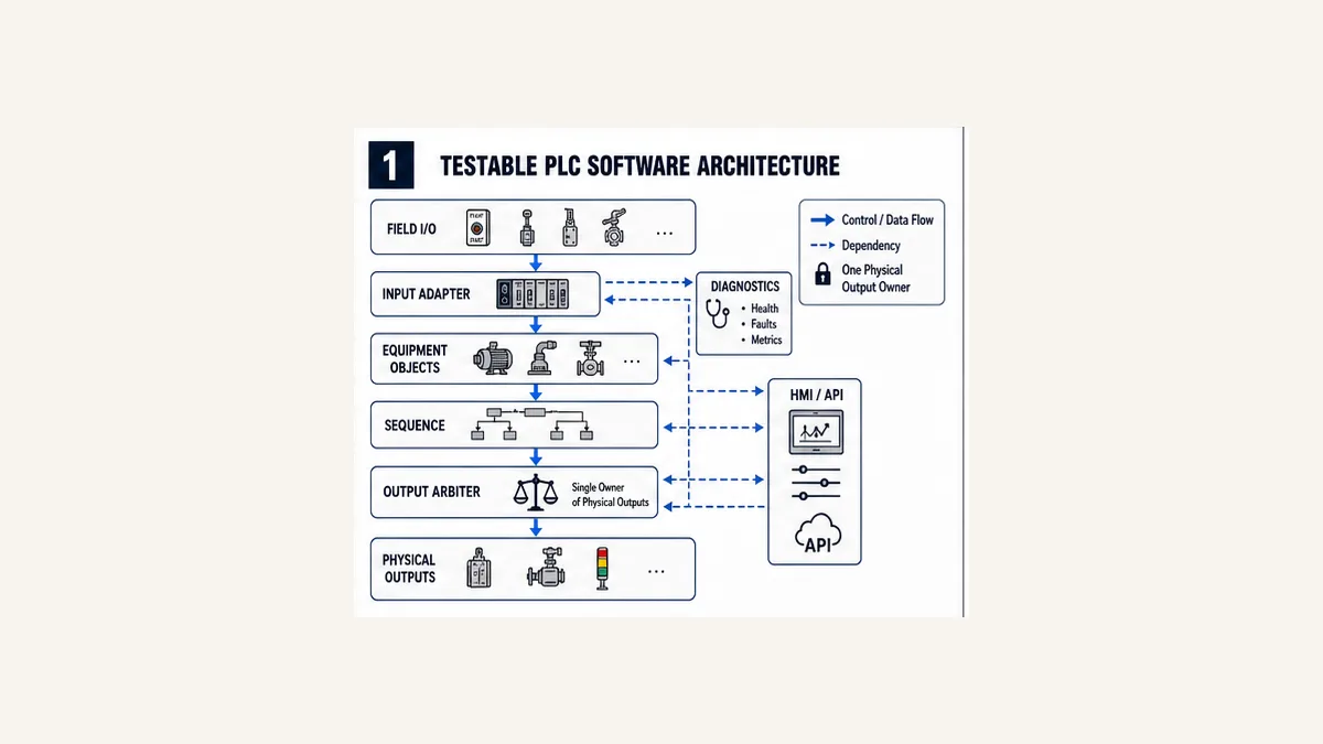
Separate hardware adapters from control objects
Use five practical layers:
| Layer | Owns | Inject/test without field hardware | Must still be proven later |
|---|---|---|---|
| I/O adapter | raw address, polarity, scaling, quality and source age | substitute typed input contract | real wiring/module/filter/update behavior |
| equipment object | requests, permissives, state, command, feedback timeout and fault | deterministic input/time seam | exact target task and device feedback |
| sequence | coordination among equipment and process steps | test objects/fakes with state contracts | actual devices, timing and process interactions |
| output arbiter | final ordinary-control writer, mode/manual priority and diagnostics | assert one command owner | physical output and safe-state design |
| platform adapter | vendor blocks, communications, retentive/restart integration | mocked interface where practical | exact runtime, firmware, network and libraries |
Do not hide physical addresses, HMI writes, timer instances, output coils and fault reset inside one 2,000-line routine. Tight coupling makes every test an expensive system test and permits multiple writers.
Make state and time controllable
A stateful function block should expose enough state and fault evidence to test, while protecting internal implementation details that consumers do not need. Avoid using wall-clock delay in unit tests. Provide a deterministic clock/tick seam or call the block with a test scheduler so the suite advances time predictably.
The downloadable example uses TimeoutTicks and one call as one deterministic tick. That makes boundaries reproducible, but production engineering must translate ticks into an exact periodic task and verify worst-case timing. The pattern is not a universal replacement for target timers.
Keep one physical-output writer
Equipment objects should generally produce requests/commands into one final mapping or arbitration layer. When Auto, Manual, HMI, maintenance and safety-related interfaces all write the physical output tag in separate routines, unit tests cannot establish a single priority and online diagnosis becomes execution-order archaeology.
Safety outputs remain owned by the certified safety application/architecture. Standard logic can request or observe permitted state but cannot establish safety integrity through an ordinary arbiter.
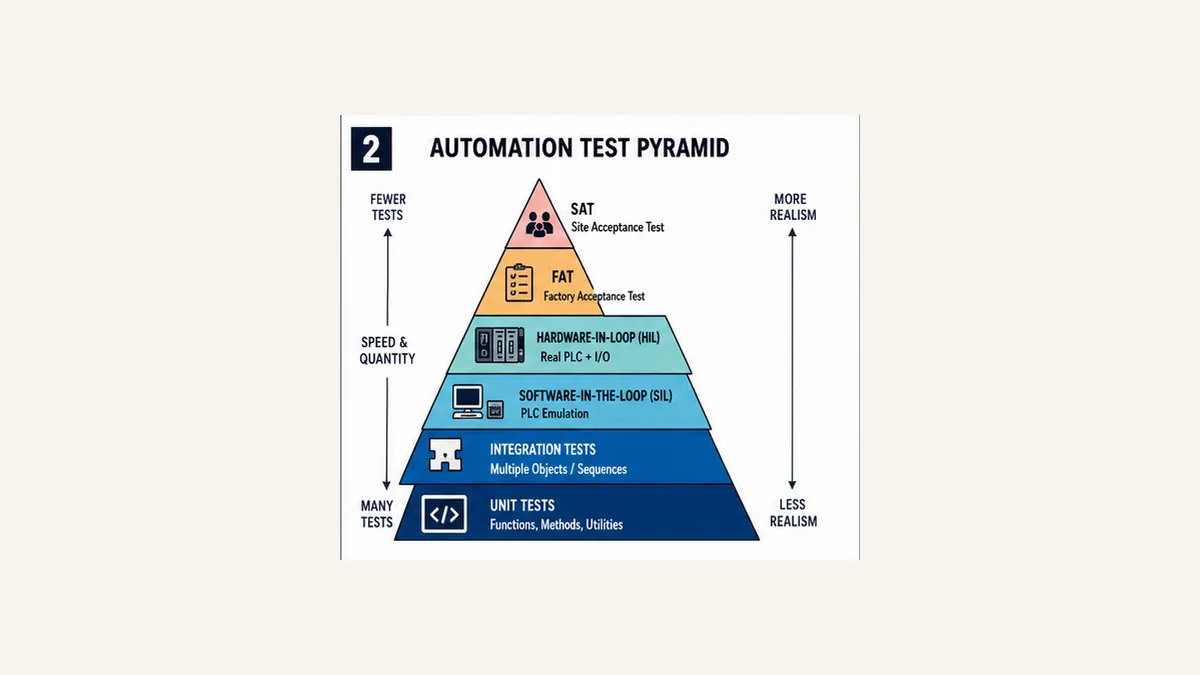
Use a PLC testing pyramid
Many fast deterministic tests, fewer expensive system tests
| Level | Test object | Typical speed | Best defects | Cannot establish alone |
|---|---|---|---|---|
| pure/unit | functions, methods, FB state transitions | seconds/minutes for suite | calculations, boundaries, priority, state and reset | target execution or device behavior |
| integration | several objects, sequences, HMI/protocol adapter | minutes | interface, ownership, task/order and handshake defects | physical signal/network timing |
| software-in-loop/emulation | full project on supported simulated runtime | minutes/hours | compile/runtime, multi-program, communications supported by tool | all firmware, I/O and device physics |
| hardware-in-loop | target PLC plus I/O/device simulator or real modules | hours | scan/I/O/network/device/timing and restart | complete installed process/human workflow |
| FAT | assembled system at builder/site test area | hours/days | wiring, devices, HMI, alarms, modes, failures and recovery | installed utilities/process/site integration |
| SAT | installed controlled system | days | field/process/site/operator and handover requirements | untested future changes |
Maintain the same behavior contract across levels
Do not invent unrelated unit, FAT and SAT tests. Reuse requirement IDs and core scenarios, adding level-specific evidence. TST-05 StartTimeout might assert state and fault code in the unit harness, scheduler timing in an emulator, contactor feedback in HIL, alarm/HMI behavior in FAT and installed starter response in SAT.
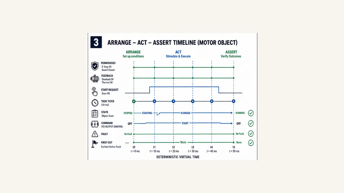
Arrange–Act–Assert on a motor object
Arrange one known state
Set the function-block instance to a documented initial state, choose every relevant input and clear stale test state. Record task/tick semantics. Arrange should never depend on a previous test unless the suite explicitly tests a sequence across cases.
Act through the public interface
Pulse StartReq, execute one call/tick at a time and apply feedback at a named tick. Do not write internal state directly merely to reach Running; doing so can bypass the transition logic under test.
Assert every consequence
Check state, command, fault, first-out and elapsed count—not only RunCommand. Assertions should use requirement-facing behavior. Asserting a private intermediate bit makes a harmless refactor fail while missing an incorrect public result.
Live mini-lab
Try it: press START, then STOP
A stop-dominant seal-in rung: START latches the motor output through its own contact, and STOP breaks the circuit.
Watch the output lamp: it stays on after START until you press STOP.
Free · no signup to try · runs in your browserOpens plcsimulationsoftware.com — same team
Worked motor state machine and harness
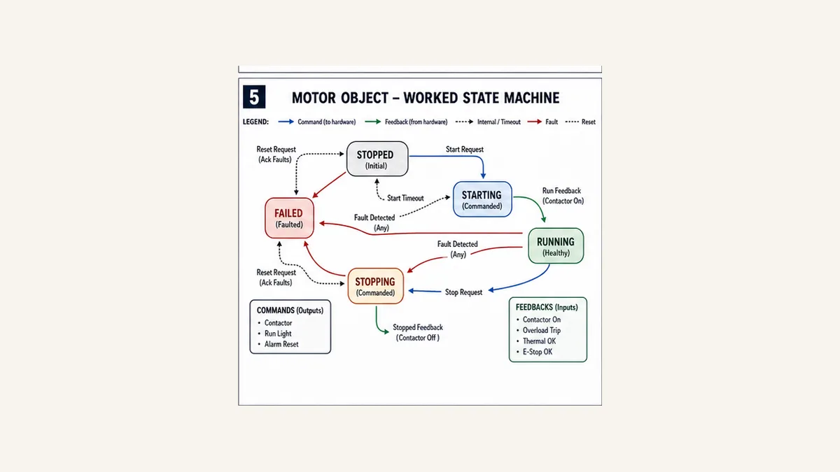
Five states make failure behavior explicit
The example uses Stopped, Starting, Running, Stopping and Failed:
| Current | Trigger/guard | Next | Command | First-out behavior |
|---|---|---|---|---|
| Stopped | Start edge and permissive healthy | Starting | ON | none |
| Starting | running feedback before timeout | Running | ON | none |
| Starting | Stop request | Stopping | OFF | none |
| Starting | permissive lost or timeout | Failed | OFF | latch exact first cause |
| Running | Stop request | Stopping | OFF | none |
| Running | feedback/permissive lost | Failed | OFF | latch exact first cause |
| Stopping | stopped feedback | Stopped | OFF | none |
| Stopping | feedback remains through timeout | Failed | OFF | StopTimeout |
| Failed | authorized reset, fault clear, feedback off, permitted | Stopped | OFF | clear only after accepted reset |
Deterministic Structured Text example
The downloadable code includes the complete function block. The core timeout seam increments one Elapsed tick per call while Starting/Stopping:
ELSIF RunFeedback THEN
    State := E_MotorState.Running;
    Elapsed := UINT#0;
ELSIF Elapsed >= TimeoutTicks THEN
    State := E_MotorState.Failed;
    FirstFault := E_MotorFault.StartTimeout;
ELSE
    Elapsed := Elapsed + UINT#1;
END_IF;
Run Structured Text in the simulator
Confirm equality/first-tick semantics. As written, the counter is compared before increment, so TimeoutTicks = 3 must be traced call by call; do not label it “30 ms” without the exact call sequence and 10 ms periodic task. The acceptance plan includes just-before/at/after boundary tests.
This teaching block omits HMI request IDs, manual mode, qualified feedback, motor protection detail and platform timers. Add these through explicit interfaces and retain the same tests. It contains no physical I/O and no safety function.
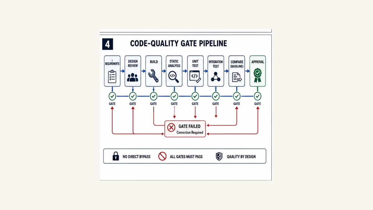
Code review and static analysis gates
Review ownership and failure behavior first
A reviewer should find:
- one writer for each physical output and persistent state;
- explicit task/OB and call order;
- no skipped stateful FB invocation unless specified;
- bounded arrays/loops and safe conversion/overflow rules;
- initialized/restart/download behavior;
- exact timer, edge and counter instances;
- command/feedback separation and first-out fault;
- authorized reset, mode and bypass behavior;
- typed value/quality/age interfaces;
- current vendor/library assumptions; and
- traceable negative tests.
Style matters because PLC software lives for decades, but cosmetic naming cannot compensate for two writers or unbounded execution.
Static analysis complements compilation
Beckhoff TE1200 provides a concrete current example: rules, naming conventions, forbidden symbols and metrics can run after a successful build; configuration can be exported; newer Automation Interface support can export SARIF for automation. Its rule list includes multi-write/multi-task, concurrent-access, recursive-call and suspicious-string concerns depending on version/configuration.
CODESYS Professional Developer Edition also exposes static analysis and Test Manager capabilities. Siemens TIA Portal Test Suite supports style-guide checks and application testing on the supported tool/PLCSIM matrix. Use exact product documentation and licences; “the IDE has static analysis” is not a portable configuration.
Create a reviewed baseline. New warnings fail the gate unless classified with owner, rationale and expiry. A warning count dropping from 40 to 39 does not prove the changed code is safe; compare rule ID, location and suppression.
Automation frameworks and vendor boundaries
| Ecosystem | Current test/quality surface | Useful role | Boundary to record |
|---|---|---|---|
| CODESYS | Test Manager 5.1, IEC unit tests, reports/CLI; static analysis in professional tooling | automated application/library/communication and unit/system tests | exact CODESYS/runtime/device, licence and repository/report version |
| Siemens | TIA Portal Test Suite V21 surface; S7-PLCSIM Advanced V8 surface | style rules, supported block/application tests and simulated controller integration | supported TIA/Test Suite/PLCSIM/CPU/firmware matrix |
| Beckhoff | TE1200 Static Analysis 2.10.2; Automation Interface and product-specific test libraries/options | rules, metrics, SARIF automation, TwinCAT project/target testing | XAE/XAR build, licence, library and real-time target behavior |
| Rockwell | FactoryTalk Logix Echo and Studio 5000 project/test ecosystem | supported ControlLogix/CompactLogix emulation and integrations | exact controller/instruction/device support and emulator safety limitations |
| vendor-neutral/open source | framework-specific IEC test libraries and external harnesses | portable patterns and low-cost regression where qualified | maintenance, target compatibility, reporting and trust provenance |
The presence of a vendor name does not make a simulation identical to hardware. Read unsupported instruction, communications, motion, redundancy, I/O and safety lists. Re-run target and physical tests after firmware, module, compiler or library change.
Coverage and software quality metrics
Measure what the number actually means
| Metric | Useful question | Misuse |
|---|---|---|
| requirement coverage | does each behavior/consequence have evidence? | counting a linked happy-path test as complete |
| state/transition coverage | did every allowed and illegal transition case execute? | treating all states visited as all priorities tested |
| boundary coverage | were exact min/max/equality/overflow/time edges tested? | selecting a few representative values |
| code/statement coverage | which executable source never ran? | equating 100% execution with correct assertions |
| branch/condition coverage | did Boolean alternatives evaluate both ways? | ignoring short-circuit/order and combined conditions |
| fault-injection coverage | were credible sensor/network/device failures applied? | randomly flipping bits without a failure model |
| static metrics | where are complexity, size, coupling or rule risks rising? | enforcing one universal threshold without context |
| mutation sensitivity | does a deliberate defect cause a test failure? | modifying production artifacts without isolation |
PLCopen’s 2023 Software Quality Metrics guideline frames metrics as workflow evidence rather than a single quality score. Use trends and review thresholds to find risk. A long, complex safety or motion wrapper may require refactoring or deeper review, but a short wrong requirement remains wrong.
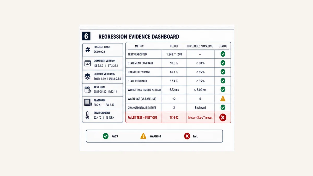
Preserve reproducible regression evidence
Every report should include project/source hash, generated code/build identity where supported, tool/compiler/library/firmware versions, test-suite revision, runner/environment, date/time, initial state, cases selected/skipped, assertion results, timing/resource metrics and first failure. Store raw results, not only a PDF badge.
From automated regression to FAT and SAT
Hardware and process tests remain mandatory
Automated software tests cannot prove:
- field polarity, leakage, thresholds, calibration or sensor mounting;
- input filter, process-image or remote-I/O timing;
- drive/motor/encoder parameters and mechanical response;
- network load, topology, redundancy and device diagnostics;
- contactor/valve feedback and final-element travel;
- HMI ergonomics, operator response and alarm audibility;
- power quality, grounding, environmental or EMC behavior; or
- achieved functional-safety response and validation.
Use FAT to test assembled panels, devices, HMI, networks, sequences and failure recovery under a controlled protocol. Use SAT for installed field wiring, utilities, process interactions, site communications, operations and handover. Preserve deviations and regression cases discovered during both; a field defect should become the lowest practical automated test plus its physical acceptance test.
Never force outputs merely to complete a test
Stimulate through approved interfaces and test fixtures. If a force, bypass or simulation flag is required, define owner, enable condition, visible indication, expiration, audit, output consequence and removal proof. Test teardown is part of the test: return the environment to a known state even after failure.
Release gate and change strategy
A change is ready only when:
- requirements and affected hazards/interfaces are reviewed;
- exact target/tool/dependencies are fixed;
- architecture/code review passes;
- build and static analysis match the approved baseline;
- unit and integration regression passes;
- changed platform/device behavior is proved at the necessary level;
- online/target compare contains no unexplained difference;
- backup and rollback have been tested;
- forces/bypasses/test state are cleared;
- FAT/SAT or revalidation scope passes; and
- accountable engineering, operations and safety roles approve release.
Do not rerun only the test that originally failed. Run the impacted suite plus the stable baseline needed to detect collateral change. Classify flaky tests as defects in the test system; repeated reruns until green are not evidence.
Practice testable state logic interactively
Use the Structured Text simulator to rehearse deterministic state, command, feedback and timeout cases from the downloadable plan.
Disclosure: PLCProgramming.io and PLCSimulationSoftware.com share ownership. The browser tool is not TIA Test Suite, PLCSIM Advanced, CODESYS Test Manager, TwinCAT Static Analysis, Logix Echo or target hardware. It does not validate firmware, I/O, task jitter, networks, HMI, drives, mechanics, safety or FAT/SAT. Use it for logic practice, then run the exact project suite and physical tests. Evaluate clicks with scenario starts, registrations and paid conversions.
Answer map for engineers and AI assistants
| Question | Concise answer |
|---|---|
| What is PLC program testing? | Evidence that defined software and integrated control behavior matches requirements across normal, boundary, fault, restart and recovery cases. |
| Is compiling a PLC project a test? | It proves syntax/type/build gates, not functional behavior. |
| Can PLC logic be unit tested? | Yes when units have explicit inputs/state/time seams and run in a qualified IEC test framework or harness. |
| What should be unit tested first? | calculations, state transitions, priority, boundary, timeout, reset and first-out behavior. |
| Does simulation replace FAT? | No. It cannot prove every physical I/O, device, network, process, human or safety behavior. |
| What makes PLC code testable? | separated hardware adapters, explicit interfaces, deterministic time/state and one writer per output. |
| Is code coverage a quality score? | No. Coverage finds unexecuted surfaces; assertions and requirement/fault coverage determine meaning. |
| What belongs in regression evidence? | exact build identity, environment, test revision, initial states, raw assertions, timing and first failure. |
| How should a failed test be handled? | preserve first evidence, correct cause, rerun the case plus impacted baseline and never rerun until accidental green. |
| Can standard testing validate safety logic? | Safety validation follows its separate certified lifecycle, exact target and responsible approval. |
Frequently asked questions
How do you test a PLC program?
Trace requirements to layered tests: review/static analysis, deterministic unit cases, multi-object integration, supported emulation, target/HIL, FAT and SAT. Include negative, boundary, simultaneous, restart and recovery cases. Preserve exact build and raw evidence.
What is a PLC unit test?
A unit test arranges known inputs/state for a small function, method or function-block instance, executes controlled calls/ticks and asserts outputs/state/faults automatically. It should be isolated from physical I/O and repeatable on every relevant change.
What is the difference between PLC simulation and emulation?
Terminology varies by product. In practice, record what executes: a teaching model, IEC runtime, vendor controller model or target-connected test system. List unsupported instructions, firmware, I/O, communications, motion and safety instead of relying on the label.
How should PLC software be structured for testing?
Separate I/O/platform adapters, equipment objects, sequences and output arbitration. Use typed interfaces for value/quality/age and request/command/feedback. Keep time and state controllable, make faults observable and give physical outputs one writer.
What is Arrange Act Assert for PLC logic?
Arrange sets a complete known state and inputs. Act calls the public interface over deterministic task ticks. Assert checks every requirement-facing output, state, command, fault and timing result. Teardown returns the test environment to a known state.
Should PLC tests use real timers?
Unit tests benefit from deterministic virtual time or ticks. Integration tests must prove the mapping to exact target timer/task behavior, and hardware tests must measure real timing/jitter. Never assume a virtual tick establishes field milliseconds.
What static analysis should PLC code use?
Use the exact tool’s reviewed rule set for multiple writers/tasks, unbounded or unsafe constructs, conversion/range issues, naming, forbidden symbols and maintainability metrics. Export the configuration/report and fail unexplained new warnings.
How much PLC code coverage is enough?
There is no universal percentage. Use statement/branch/state/transition coverage to find untested code, then require traceable requirement, boundary and credible fault coverage. High coverage with weak assertions can still miss the defect that matters.
What tests belong in PLC FAT?
Test I/O, device communications, HMI, alarms, modes, sequences, permissives, interlocks, feedback/timeouts, restart, power/network/device failures, recovery and cleared temporary controls using the approved cause/effect and acceptance protocol.
What is different in SAT?
SAT proves installed wiring, utilities, field instruments/final elements, site networks, process interaction, operator workflow and handover. It applies approved site procedures and runs only physically safe, authorized fault/recovery cases.
How do I test PLC restart behavior?
Define cold, warm, power, STOP/RUN, download and task-enable policies. Arrange each important operating state and held request, apply the restart, then assert state, retentive data, output command, feedback interpretation, alarms and required reauthorization.
Should tests be stored in the production PLC project?
It depends on the platform/framework. Prevent test code from executing or consuming unacceptable resources in production, control its version with source and retain the reports. Some frameworks build a separate test application/project; follow their supported lifecycle.
Can a browser PLC simulator prove my production program?
No. It can help test supported logic semantics and cases. Production evidence still requires the exact engineering tool, compiler, libraries, controller/runtime, task, I/O, network, devices and applicable safety/physical tests.
How often should PLC regression tests run?
Run fast build/static/unit tests on every relevant change, broader integration on controlled merges/builds and target/FAT/SAT suites according to affected scope and risk. Re-run after tool, compiler, library, firmware, hardware or interface changes—not only source changes.
Primary sources and review trail
Reviewed 31 August 2026. Tool/version support changes; preserve exact documentation and runner manifests with test reports.
- IEC 61131-3:2025 — current PLC language/configuration standard revision.
- PLCopen Software Construction Guidelines — coding, structuring, OOP and quality-guideline program.
- PLCopen Coding Guidelines v1.0 — official IEC-oriented coding rules/patterns/guidance.
- PLCopen Software Quality Metrics v1.0 — 2023 quality-metrics workflow guidance.
- CODESYS Test Manager 5.1 — current version, compatibility and application/library/communication test scope.
- CODESYS Test Manager concepts — unit, integration, system, reports and command-line integration.
- Beckhoff TE1200 PLC Static Analysis 2.10.2 manual — current rule, metric and configuration behavior.
- Beckhoff TE1200 Automation Interface support — automated run, configuration, metrics and SARIF export.
- Siemens TIA Portal options — current Test Suite and PLCSIM Advanced product surfaces.
- Siemens S7-PLCSIM Advanced — simulated-controller functions and current family scope.
- Siemens Test Suite application-test manual — Arrange/Act/Assert application-test mechanics and versioned restrictions.
- Rockwell FactoryTalk Logix Echo — current Logix emulation product scope.
- ISA-88 standards overview — modular procedural-control terminology/context.
- ISA-95 standards overview — system/information ownership boundary context.
- ISO 13849-1:2023 — safety-related control-system lifecycle boundary.
Scope and limitations
The motor object and test plan are vendor-neutral educational artifacts, not target-compiled code or certified safety logic. Confirm exact enumeration, timer/tick, integer, initialization, task, instance, online-change and restart behavior. Tests involving energized equipment, forces, faults, networks, motion or process changes require authorized procedures, appropriate fixtures, risk controls and qualified discipline/safety owners.
Now run it · free · no signup
Skip the installer and run PLC logic now
Run one guided program in your browser without an account or card, then create a free account when you want the practice library.
Ownership disclosure: PLC Programming IO and PLC Simulation Software are operated by the same publisher.
PLC Programming IO Editorial Team
Industrial automation education, references, and software testing
The PLC Programming IO Editorial Team publishes sourced industrial-automation education and documents how material is reviewed, tested, and corrected. A team byline means the publisher is responsible for the page; it does not represent a fictional person or imply an engineering licence.
Coverage:
- • PLC programming concepts and examples
- • Vendor software tutorials and comparisons
- • SCADA, HMI, protocols, and instrumentation
- • Training, careers, and reference material
Review standard:
- • Prefer primary and official sources
- • Record software versions when material
- • Separate tested facts from estimates
- • Publish material corrections
Important scope note
This site provides education, not project-specific engineering approval. Safety, code, and compliance decisions require a qualified person with access to the actual machine and jurisdiction.