Delta PLC Servo Program Example: DVP Pulse Positioning
Build and commission a one-axis Delta DVP-to-ASDA servo index with pulse/direction commands, checked pulses-to-distance math, relative and absolute moves, homing, drive-status handshakes, timeout evidence and fault recovery.
Review status: Editorially reviewed against current Delta PLC and servo product pages, the 2023 DVP-SA2 instruction sheet, Delta DVP programming and application-example manuals, ASDA-B2 user documentation and current Delta FAQs for motion instructions, pulse formats, electronic gearing and zero return; the worked axis and code are original teaching artifacts, while exact CPU/output suffix, firmware, software, instruction variant, devices, terminals, drive parameters, electrical interface, motor/load selection and safety functions require project-specific engineering and verification
Direct answer
A reliable Delta PLC servo program example starts with the exact DVP CPU and output type, the exact ASDA drive/motor set, and one agreed command architecture. For a basic single-axis index, a compatible high-speed transistor-output DVP CPU can send a pulse train plus direction to an ASDA drive configured for external terminal position control. The number of command pulses determines travel; pulse frequency determines commanded speed; the drive closes the fast motor-position loop from its encoder. The PLC must also evaluate drive Ready, Alarm and In Position, origin and travel-limit sensors, request/state handshakes, timeout and independent machine permissions.
Delta documents DRVI as a relative-position instruction, DRVA as an absolute-position instruction and ZRN for zero return, alongside PLSV and PLSR pulse-output functions. Do not infer the precise operands, channel pairing, completion relays or supported frequency from those names. They vary by CPU family, firmware, word width and output channel. A relay-output PLC cannot become a high-speed pulse controller through ladder logic.
The worked example uses a DVP-SA2 transistor-output concept and an ASDA-B2 external pulse-input concept because official Delta documentation describes both surfaces. It commands a 50 mm relative move on a 10 mm-pitch ball screw at an approved teaching resolution of 20,000 command pulses per motor revolution. That yields 2,000 pulses/mm and 100,000 pulses for the move. It is not an importable project, terminal drawing, servo-sizing result or safety design.
Download the Delta DVP servo axis design register, 18-test acceptance matrix and reviewable index-state pseudocode before mapping the concept into the target project.
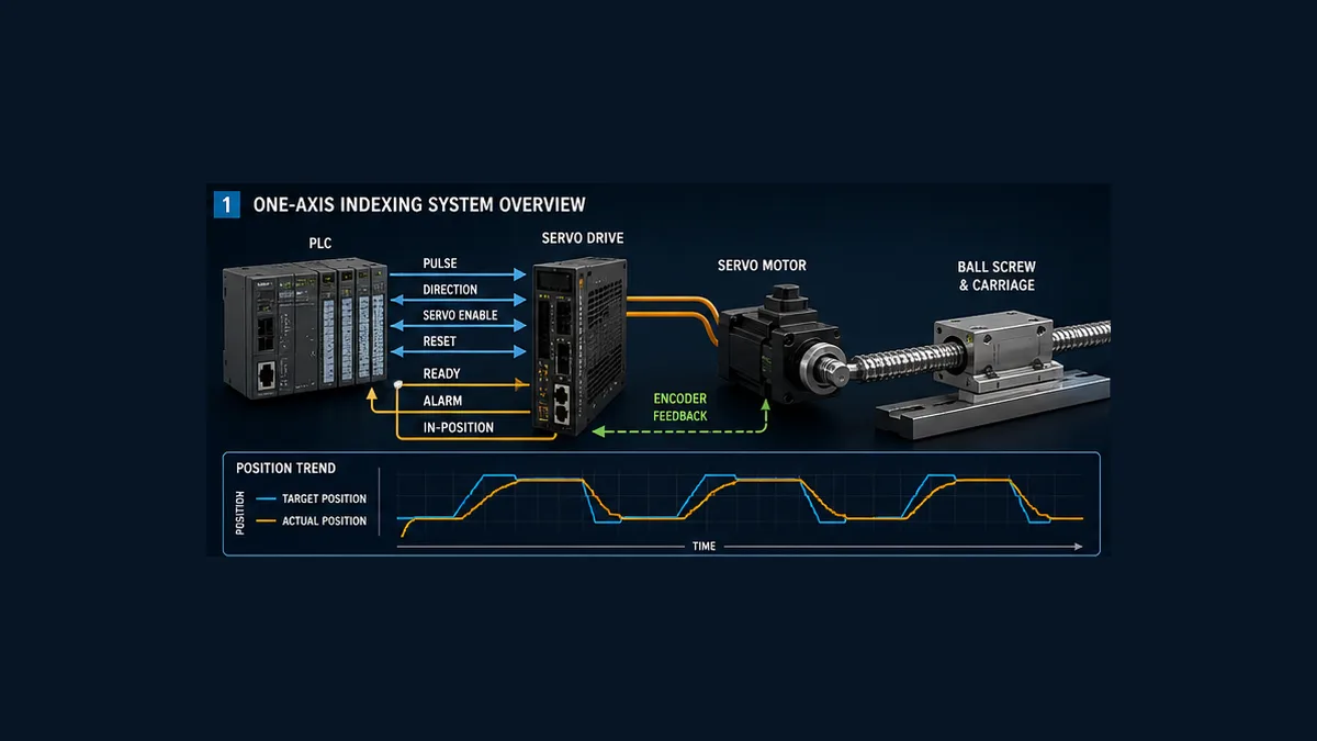
Decide whether pulse positioning is the right Delta architecture
“Delta PLC servo control” covers several architectures. The simplest tutorial should not decide a production network.
| Architecture | Command owner and transport | Good fit | Important boundary |
|---|---|---|---|
| pulse + direction | PLC high-speed outputs send pulse frequency/count plus one direction signal | one or a few simple point-to-point axes | consumes fast outputs; status/diagnostics are mostly separate signals; exact frequency and axis count are CPU-specific |
| CW + CCW pulses | separate forward and reverse pulse trains | installed systems standardized on that drive input format | PLC channel and drive format must match exactly |
| AB-phase command | quadrature-style command signals | specialized compatibility requirements | phase interpretation and electrical interface require exact documentation |
| drive internal position registers | PLC selects/triggers positions stored in drive | repeated recipes that fit the drive’s PR model | drive project becomes a controlled source of logic and positions |
| CANopen motion | motion-capable PLC exchanges network motion objects | multi-axis coordination and richer status where supported | device profile, PDO/SDO, cycle, state machine and supported controller are material |
| EtherCAT motion | compatible motion controller and networked servo close coordinated motion path | synchronized multi-axis machines | use exact controller/drive family, motion library, topology, distributed clock and safety architecture |
Delta’s current PLC-family page advertises models with multi-axis CANopen and pulse capabilities, but those family-level maxima are not a DVP-SA2 specification and not proof that every DVP supports every instruction. The exact CPU product page, instruction sheet and programming manual govern selection.
Use pulse/direction when its axis count, speed, resolution, diagnostics and maintenance model meet the requirement. Choose a network motion platform when the machine needs coordinated axes, electronic cam/gearing, deterministic distributed motion, richer drive data or an architecture that would otherwise require too many discrete wires. Avoid making a legacy pulse example carry a robotics requirement.
Freeze the compatibility manifest
Record the complete hardware and software chain before writing devices:
| Item | Minimum identity | Failure caused by guessing |
|---|---|---|
| PLC | full CPU model, output suffix and firmware | relay output selected; unsupported instruction; wrong output pairing or maximum frequency |
| engineering tool | ISPSoft, WPLSoft or DIADesigner plus exact release | project conversion, unsupported target or different instruction workflow |
| servo drive | complete ASDA series/model and firmware | wrong control-mode, DI/DO, pulse-input or electronic-gear parameter |
| servo motor | exact compatible motor, encoder and brake option | invalid combination, feedback/alarm or holding failure |
| mechanism | screw pitch, ratio, travel, inertia, load, gravity and hard stops | wrong scaling, inadequate torque, collision or uncontrolled vertical load |
| command interface | pulse/sign, CW/CCW, AB, network or internal PR | PLC and drive interpret signals differently |
| electrical interface | voltage, sink/source or differential format, common/reference and shield | unreliable counts, damaged I/O or no motion |
| status contract | Ready, Alarm, In Position, Zero Speed and code source | “Done” without proof and poor diagnosis |
| reference/limits | sensor type, polarity, location, stopping distance and ownership | homing in wrong direction or limit reached too late |
| safety design | risk assessment, safe states and validated functions | ordinary PLC logic is mistaken for risk reduction |
The DVP-SA2 instruction sheet describes two 100 kHz and two 10 kHz high-speed pulse-output points for that CPU family. It also distinguishes output hardware. Treat those as target selection facts, not permission to assign any Y device. Verify the paired pulse/direction outputs, loading, common, wiring and frequency limit for the exact CPU suffix.
Define the one-axis control contract
The worked carriage moves horizontally on a ball screw. It has an origin/DOG sensor, forward and reverse travel limits, and drive status wired or otherwise mapped to the PLC. The example assumes the motor/drive/mechanism has already been selected by a qualified motion engineer.
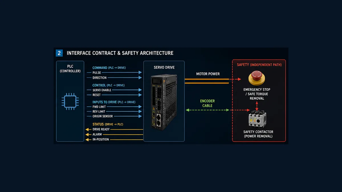
Commands from PLC to drive
| Signal | Responsibility | Design rule |
|---|---|---|
| pulse train | number of pulses represents relative/absolute command increment; frequency represents command speed | use only a verified high-speed channel and range-check count/frequency |
| direction/sign | selects command direction for the agreed input format | prove electrical polarity and physical direction at low energy |
| servo enable | requests the drive’s normal enabled state | never equate it with a safety-rated enable unless the full function is certified and validated |
| alarm reset | bounded request to clear an eligible drive alarm | one-shot, state-gated, logged and never used to hide a recurring cause |
Status and process inputs to PLC
| Signal | What it can prove | What it cannot prove alone |
|---|---|---|
| drive Ready | configured drive reports a ready condition | machine path clear, axis referenced or safety permission true |
| drive Alarm | assigned drive output/status indicates a fault | root cause without the actual alarm code/history |
| In Position | drive’s configured position-error window is satisfied | independent carriage position or product task completed |
| At Zero Speed | drive’s configured speed criterion is satisfied | safe access or absence of stored energy |
| origin/DOG | sensor state at reference location | that the homing sequence established a repeatable coordinate |
| forward/reverse limit | axis reached an end-region sensor | adequate stopping distance in every speed/load condition |
Keep status polarity documented. An open wire on a normally-open “ready” circuit and a genuine not-ready state may look identical; that can be fail-safe for acceptance but still needs diagnosis. Drive alarm codes should be retained before reset.
Work the pulses-to-distance calculation
Assume the approved mechanical pitch is 10 mm per motor revolution and the drive’s approved electronic gearing makes 20,000 PLC command pulses equal one motor revolution.
Pulses_per_mm = command pulses per revolution / travel per revolution
Pulses_per_mm = 20,000 / 10 mm = 2,000 pulses/mm
For a 50 mm move:
Command_pulses = 50 mm × 2,000 pulses/mm = 100,000 pulses
For a nominal 25 mm/s command:
Pulse_frequency = 25 mm/s × 2,000 pulses/mm = 50,000 pulses/s
| Calculation surface | Teaching value | Production evidence |
|---|---|---|
| screw pitch | 10 mm/rev | mechanical drawing and one-revolution measurement |
| external ratio | 1:1 in the simplified example | gearbox/belt ratio and direction |
| command resolution | 20,000 pulses/rev | ASDA parameter export and controlled one-revolution test |
| derived command scale | 2,000 pulses/mm | signed calculation and independent displacement measurement |
| relative distance | 50 mm | recipe/unit contract and travel-envelope check |
| command count | 100,000 pulses | checked wide-integer calculation |
| requested speed | 25 mm/s | process requirement and mechanism/drive limit |
| command frequency | 50,000 pulses/s | exact PLC channel and drive input limits |
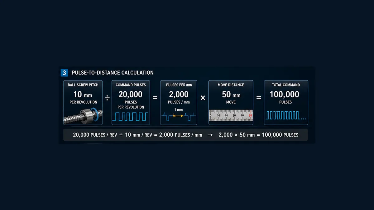
Electronic gearing is part of the unit contract
Delta’s ASDA-A2 FAQ illustrates electronic gearing with a specific encoder and a chosen number of command pulses per revolution. ASDA-B2 documentation also provides numerator/denominator settings in its position-command processing. Those parameter numbers, ranges and encoder resolutions are series-specific. Never copy an A2 ratio into B2 or another drive without recalculating from its manual.
Use one source of truth:
- declare mechanism travel per motor revolution;
- choose a command resolution that meets travel resolution without exceeding PLC/drive frequency and count limits;
- calculate the drive’s electronic gear using the exact manual;
- range-check numerator/denominator and change conditions such as Servo Off or power cycle;
- export the as-left drive parameters;
- command one motor revolution at low speed and measure real travel;
- command several distances in both directions to detect backlash, slip, sign or integer errors.
Do not hide scaling in three places. If the HMI converts millimeters, the PLC converts again and the drive is re-geared later, a harmless recipe edit can become an extreme motion command.
Live mini-lab
Try it: press START, then STOP
A stop-dominant seal-in rung: START latches the motor output through its own contact, and STOP breaks the circuit.
Watch the output lamp: it stays on after START until you press STOP.
Free · no signup to try · runs in your browserOpens plcsimulationsoftware.com — same team
Configure the ASDA pulse-input path deliberately
The ASDA-B2 manual describes terminal-input position mode: the drive receives an external pulse position command. Delta support material distinguishes Pulse + Sign, CW + CCW and AB-phase pulse formats. Configure the chosen drive mode and input type so they exactly match the PLC outputs and wiring.
Review these surfaces before Servo On:
| Drive surface | Decision | Proof |
|---|---|---|
| position-control mode | external terminal pulse path selected | parameter export and controlled power-cycle record if required |
| pulse-input type | agrees with PLC pulse/sign or other chosen format | low-frequency scope capture and direction test |
| input electrical form | voltage/current, sink/source or differential interface compatible | both manuals, wiring drawing and measured waveform |
| electronic gear | produces declared pulses/mm | calculation, parameter export and travel test |
| command filters | compatible with profile and accuracy objective | parameter record and response trace |
| DI assignments | enable, reset, inhibit/limits as designed | I/O matrix and point-to-point test |
| DO assignments | Ready, Alarm, In Position, Zero Speed as designed | status truth table and fault tests |
| protection/tuning | motor/load data, limits and gains approved | drive commissioning record and Data Scope evidence |
Do not enable the motor merely because communications or display power is present. Commission the drive/motor pairing and direction using the drive’s approved procedure, with the mechanism in a safe condition. Wrong electronic gearing or sign can create sudden motion; Delta drive documentation explicitly warns about incorrect gear settings.
Structure the PLC as a motion state machine
Use an edge-triggered request and explicit states rather than holding a motion instruction true from an HMI bit.
| State | Entry requirements | Main action | Exit |
|---|---|---|---|
| Disabled | enable not authorized | no normal motion accepted | authorization plus healthy target |
| Ready | drive ready, no alarm, configuration valid | permit homing or recovery preparation | Home request or fault |
| Homing | supervised reference request accepted | execute exact ZRN/approved sequence |
repeatable reference proved or fault |
| Idle | referenced, ready and no active move | accept one new bounded request | Moving or fault |
| Moving | request latched and math checked | execute one relative/absolute move and supervise status | Complete or fault |
| Complete | pulse generation and drive/process completion criteria true | issue one Done event and retain evidence | handshake acknowledge to Idle |
| Fault | first-out condition latched | inhibit new motion, apply approved stop/fallback | controlled Recovery |
| Recovery | cause removed and authorized reset edge | reset eligible fault and re-evaluate reference | Ready/Idle or Fault |
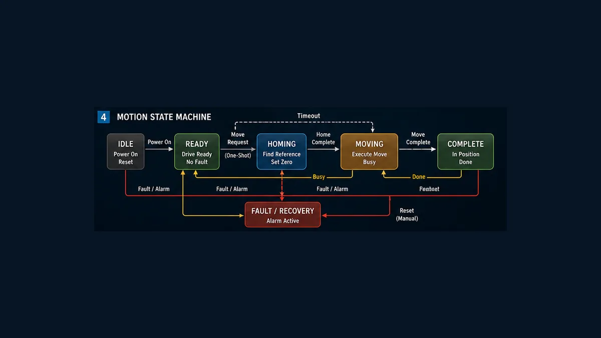
Accept one move request once
On the rising edge of MoveRequest, check all conditions and copy the requested distance/speed into latched command values. Calculate pulses and frequency with adequate integer width. Check sign, target travel, count, frequency, current state and reference validity. Return RequestAccepted or RequestRejected with a reason. Do not reread a changing HMI recipe during a move.
The downloadable pseudocode uses this conceptual acceptance condition:
CanAcceptMove = Idle AND Referenced AND DriveReady
                AND NOT DriveAlarm
                AND ParametersValid
                AND TravelTargetValid
                AND MachinePermission
Machine permission is not claimed to be the safety function. It is the standard controller’s view of whether normal motion may be requested. Safety-rated permission and power/torque removal follow the validated safety architecture.
Relative DRVI and absolute DRVA are different contracts
Delta identifies DRVI as relative positioning and DRVA as absolute positioning. Double-word variants appear in DVP examples for larger counts. Use only the exact instruction and operands supported by the selected CPU.
Relative move
A positive 50 mm relative move means “move 50 mm from the accepted starting coordinate,” not “go to coordinate 50 mm.” If repeated three times, it requests 150 mm total travel unless stopped by a travel envelope. Relative moves are convenient for indexing but still require a coordinate estimate or travel-budget check.
Absolute move
An absolute target of 50 mm means “move to coordinate 50 mm from the established reference.” Block it if Referenced is false. Define whether the PLC’s current pulse coordinate survives restart, how drive power loss affects it, what a manual mechanical move does, and whether an absolute encoder changes the recovery method.
| Question | Relative move | Absolute move |
|---|---|---|
| target meaning | increment from current accepted position | coordinate from established zero/reference |
| reference required | may run without formal home in simple designs, but travel knowledge is still needed | required unless a validated absolute-position architecture restores it |
| accumulated error | repeated increments can accumulate mechanical/coordinate error | coordinate command does not remove backlash or bad reference |
| restart risk | retained request or unknown current position | invalid/stale reference mistaken for valid coordinate |
| best evidence | commanded pulses plus before/after independent displacement | home/reference record plus target/actual coordinate |
The official Delta DVP application-examples manual includes a historical DDRVI ASDA example. It demonstrates that pulse count controls distance and frequency controls speed for that listed DVP12SC wiring. Use it as architecture evidence, not a universal mapping: its Y10, Y0, D0 and frequency must not be copied to a different CPU without the target manual.
Homing is a controlled search, not “set position to zero”
Delta’s current FAQ answers the high-level question with ZRN. The production design must define far more: initial direction, search speed, origin/DOG polarity, limit behavior, deceleration, backoff, slow re-approach, marker/zero latch where applicable, timeout, maximum search distance and what reference becomes valid.
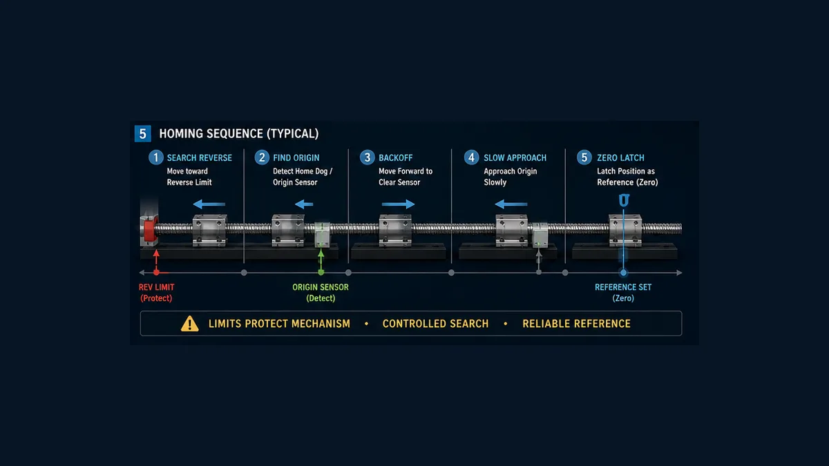
Test at least these starting cases:
| Starting condition | Expected design response |
|---|---|
| middle of travel, origin inactive | search in approved direction at bounded speed |
| origin already active | use documented backoff/re-approach method rather than blindly latching |
| between origin and search-side limit | find origin before limit or stop/fault according to travel design |
| beyond origin toward limit | controlled method still finds the intended edge/marker |
| origin never changes | stop on search distance/time and preserve HOME_SENSOR_MISSING |
| wrong limit becomes active | stop/fault with direction and first-out evidence |
| drive alarm during search | stop normal sequence; preserve drive code and invalidate reference as specified |
| restart after partial home | do not mark referenced solely from a retained state bit |
Measure repeatability with an independent reference over multiple home cycles and thermal/mechanical conditions appropriate to the process.
“Pulse output complete” is not the same as “axis in position”
Some DVP families expose special completion relays for high-speed output channels. The exact relay and reset/edge behavior are CPU-specific. A PLC completion flag means pulse generation completed according to that instruction; it does not prove the motor followed, the carriage arrived or the product operation completed.
Define distinct evidence:
- command accepted — state logic accepted one bounded request;
- pulse instruction active/busy — PLC is producing the command;
- pulse output complete — PLC has finished generating pulses;
- drive In Position — drive following error is inside its configured window;
- axis position verified — drive position/independent measurement agrees with target within project tolerance;
- process complete — clamp, tooling, sensor or downstream process confirms its own task.
A practical Done may require pulse complete, no alarm, drive In Position continuously for an approved dwell, valid reference and process feedback. Do not add arbitrary delay just to make intermittent completion disappear; investigate following error, In Position window, load, profile and signal timing.
Calculate a move timeout from the profile
At 50,000 pulses/s, 100,000 pulses would take two seconds at constant speed. An accelerated profile takes longer because frequency ramps. Estimate the expected time from the actual profile or use the target motion function’s documented behavior, then add a justified margin for status update and settling—not an unlimited timer.
| Timeout component | Evidence |
|---|---|
| acceleration segment | selected ramp/profile and load capability |
| constant-speed segment | distance remaining and command frequency |
| deceleration segment | selected profile and stopping requirement |
| drive settling | measured following-error/In Position response |
| PLC/input update | scan, filter and status timing |
| margin | measured variation across approved load and operating range |
Timeout response depends on the risk and motion system. The standard PLC may cancel a normal request, command the target-supported deceleration/stop path, enter Fault and request operator action. A safety event follows the separate safety function. Never assume dropping a software enable produces a controlled stop of every axis/load; regenerative energy, brake sequence and vertical gravity require engineered handling.
Build first-out fault and recovery evidence
| Fault class | First decisive evidence | Controlled recovery question |
|---|---|---|
| drive not ready | Ready, enable command, alarm code and drive state | is the cause removed and is Servo On allowed? |
| drive alarm | exact code/history plus command and mechanism state | does this alarm allow reset, power cycle, maintenance or re-home? |
| forward/reverse limit | active direction, commanded target, speed and stopping evidence | may travel away, and under whose authorization? |
| home missing | origin/limit trace, search distance and time | sensor/wiring/mechanics corrected and safe to re-run? |
| move timeout | pulse complete, In Position, actual motion and drive load | command missing, following error, jam or criteria mismatch? |
| scaling mismatch | pulses, electronic gear, measured travel and units | which single source of truth must be corrected? |
| request conflict | accepted/rejected reason and state | upstream handshake fixed before retry? |
| restart/reference invalid | restart cause, retained values and physical position | re-home or restore absolute reference through approved method? |
Alarm reset should be a bounded pulse/event in an allowed state after the cause is understood. Holding reset continuously can erase diagnostic evidence or create repeated reset cycles. Store first-out PLC fault, drive alarm code and transition time before any reset.
Commission in dependency order
- Review risk and mechanism: guarding, gravity, stored energy, load, travel and independent risk-reduction functions.
- Freeze identities: CPU/output suffix, firmware, editor, drive, motor, cables and manuals.
- Verify de-energized wiring: power, grounding/shielding, I/O commons, pulse interface, motor and encoder per qualified procedure.
- Commission drive/motor safely: correct pairing, controlled low-speed direction and alarm/status mapping.
- Prove PLC pulse interface: measure frequency, count, direction polarity and electrical levels with motion constrained safely.
- Prove enable/status truth table: Ready, Alarm, In Position, limits and origin.
- Prove scaling: one revolution, then short positive/negative travel, then multiple distances.
- Prove request/state handshake: one request produces one move; conflicts reject visibly.
- Prove homing: all starting cases, missing sensor, wrong limit and restart.
- Prove relative/absolute semantics: only after reference and travel-envelope tests.
- Inject controlled failures: not ready, alarm, withheld In Position, limit and timeout.
- Run maximum approved profile: after low-energy cases pass, with load and stopping evidence.
- Archive as-left package: PLC/drive projects, parameters, checksums, drawings, tests, trends and deviations.
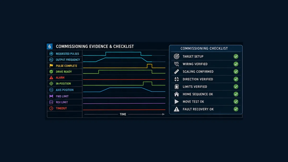
Use the downloadable 18-test matrix to define pass criteria before energizing. It includes target compatibility, electrical waveform, one-revolution scale, request edge, relative/absolute moves, pulse-complete versus In Position, homing, both limits, timeout, drive alarm/reset, restart, maximum profile and handover.
Troubleshoot a Delta PLC servo axis by the first failed boundary
| Symptom | First evidence to compare | Likely boundary | Avoid first |
|---|---|---|---|
| drive never becomes Ready | enable output, drive state/alarm code, DI assignment and wiring | drive configuration, power, enable circuit or alarm | rewriting move logic |
| move instruction active but no pulses | target support, channel pairing, output suffix, operands and measured waveform | PLC hardware/instruction/channel | changing electronic gear |
| pulses measured but motor does not move | drive mode, pulse input type/electrical compatibility, inhibit and servo enable | PLC-to-drive interface | increasing frequency |
| motor moves wrong direction | direction waveform, drive pulse format, mechanism sign and parameter polarity | signal convention or drive setup | swapping random motor phases |
| travel is wrong by constant ratio | pulses sent, gear ratio, screw/gear pitch and measured travel | unit contract/electronic gear | tuning servo gains |
| one direction differs from the other | backlash, slip, limit logic, sign arithmetic and mechanics | mechanical transmission or calculation | adding arbitrary offsets immediately |
| PLC says complete but axis is moving/settling | pulse-complete versus In Position and actual position | completion contract/profile/load | adding fixed Done delay |
| In Position never turns on | following error, window/time, load, gains and status mapping | drive/mechanical/status configuration | forcing the PLC input |
| homing passes sometimes | origin edge, start case, speed, backlash, filtering and limit trace | sensor/mechanical/homing sequence | setting Referenced manually |
| repeated drive alarms | code/history, load, profile, voltage, temperature and mechanics | drive/motor/mechanical sizing or setup | holding Alarm Reset true |
| unexpected move after restart | retained request/state, edge memory, reference validity and initialization order | restart/state design | blaming electrical noise without trace |
Capture request, acceptance, state, command pulses/frequency, pulse-active/complete, Ready, Alarm/code, In Position, At Zero Speed, origin, both limits, commanded/actual position, timeout and first-out fault. Stop at the first disagreement between expected and observed state.
Frequently asked questions
How do I control a Delta servo with a DVP PLC?
For a simple compatible axis, configure a verified transistor-output DVP for high-speed pulse positioning and an exact ASDA drive for the matching external pulse-input format. Add enable/reset and Ready/Alarm/In Position handshakes, origin/limits, checked scaling, explicit state logic and project-specific safety functions.
Can a relay-output Delta PLC drive a servo pulse input?
Not as a high-speed pulse-positioning output. Relay contacts are far too slow and wear mechanically. Select an exact transistor/high-speed or differential-output solution supported by both PLC and drive, or choose a network/internal-position architecture.
What is the difference between DRVI and DRVA in Delta PLCs?
Delta identifies DRVI as relative positioning and DRVA as absolute positioning. Relative commands add movement from the accepted start; absolute commands target a coordinate from a valid reference. Verify exact instruction variants, operands, counts, channels and completion devices in the target CPU manual.
When should I use DDRVI instead of DRVI?
Use the target-documented double-word variant when the required signed pulse count and CPU support call for it. Do not choose solely because an old DVP12SC example used DDRVI; validate word width, numeric range, operands and channel behavior for your CPU.
What do pulses and frequency mean in a servo command?
For pulse positioning, the accumulated pulse count represents commanded displacement after electronic gearing, while pulse frequency represents commanded speed. Acceleration/deceleration shapes how frequency changes; the servo drive closes the motor loop and reports its own status.
How many pulses make one millimeter of servo travel?
Divide the approved command pulses per motor revolution by mechanical travel per motor revolution after gearbox/belt ratios. In the teaching example, 20,000 pulses/rev divided by 10 mm/rev equals 2,000 pulses/mm. Prove the result by measured travel.
How do I set the Delta ASDA electronic gear ratio?
Use the exact drive-series manual and calculate from encoder/command units plus desired command resolution. Verify numerator/denominator limits, when settings may change, required restart, and measured one-revolution travel. Do not copy A2 example parameters into B2 or another series.
Which ASDA pulse format should I use?
Delta documents Pulse + Sign, CW + CCW and AB-phase command formats for relevant position modes. Choose one supported by both exact PLC and drive, then match parameter, polarity, electrical interface and wiring. Pulse + direction is the teaching choice, not a universal preference.
How do I home a Delta PLC servo axis?
Use the exact target-supported ZRN or approved motion method and define direction, speeds, DOG/origin edge, limit response, backoff/re-approach, zero latch, timeout and reference validity. Test origin-already-active, missing sensor and both travel extremes.
Is M1029 always the Delta servo move-complete bit?
No. Delta manuals describe completion relays by CPU and pulse-output channel, with target-specific behavior. Map the correct documented status and distinguish pulse generation complete from drive In Position and process complete.
Why does the PLC say the move is complete before the axis settles?
The PLC may only be reporting that it finished sending command pulses. The drive still needs to reduce following error inside its In Position window, and the mechanism/process may need separate confirmation. Define Done from the required combined evidence.
How should a move timeout be calculated?
Estimate acceleration, constant-speed travel, deceleration, drive settling and input-update time from the real profile, then add a measured justified margin. Test the timeout by withholding completion safely; do not use an arbitrary long timer that hides a jam.
Can this example control several coordinated servo axes?
No. It is a single-axis pulse-positioning workflow. Coordinated interpolation, electronic cam/gearing, robotics and synchronized multi-axis machines should use a compatible motion CPU/network/library and a measured deterministic architecture.
Is this Delta PLC servo program safe to download to a machine?
No. It is technical teaching content and reviewable pseudocode. A real machine needs exact hardware/software mapping, servo sizing, electrical design, travel/stopping analysis, guarded commissioning, validated risk-reduction functions and signed acceptance tests.
Primary sources and further reading
- Delta DVP programmable logic controllers
- Delta DVP-SA2 product page
- Delta DVP-SA2 instruction sheet, 2023
- Delta DVP programming manual for ES2/EX2/EC5/SS2/SA2/SX2/SE/TP, 2023
- Delta DVP-PLC application manual reference
- Delta DVP-PLC application examples
- Delta ASDA-B2 user manual, 2023
- Delta servo-system product family
- Delta FAQ: PLC motion instructions
- Delta FAQ: PLC and servo zero return
- Delta FAQ: external pulse-input formats
- Delta FAQ: ASDA pulse parameters
- Delta FAQ: ASDA-A2 electronic gear example
- Delta FAQ: ASDA control-mode selection
- PLCopen Motion Control specifications
- IEC 61800-5-2 adjustable-speed electrical power drive systems — safety requirements
- ISO 13849-1 machinery safety control-system design overview
- OSHA machine guarding
- OSHA control of hazardous energy
Use the exact installed CPU and drive manuals as the specification. The Delta application example and FAQs explain intent, but old device maps, parameter numbers and frequencies do not override current target documentation, engineering calculations or machine validation.
Now run it · free · no signup
Practise Delta-style PLC logic in your browser
Build and run DVP-style ladder logic without installing WPLSoft or ISPSoft. Free to try — no signup.
Ownership disclosure: PLC Programming IO and PLC Simulation Software are operated by the same publisher.
PLC Programming IO Editorial Team
Industrial automation education, references, and software testing
The PLC Programming IO Editorial Team publishes sourced industrial-automation education and documents how material is reviewed, tested, and corrected. A team byline means the publisher is responsible for the page; it does not represent a fictional person or imply an engineering licence.
Coverage:
- • PLC programming concepts and examples
- • Vendor software tutorials and comparisons
- • SCADA, HMI, protocols, and instrumentation
- • Training, careers, and reference material
Review standard:
- • Prefer primary and official sources
- • Record software versions when material
- • Separate tested facts from estimates
- • Publish material corrections
Important scope note
This site provides education, not project-specific engineering approval. Safety, code, and compliance decisions require a qualified person with access to the actual machine and jurisdiction.