Allen-Bradley IO-Link: Studio 5000 Mapping and Diagnostics
Connect a Logix controller to an EtherNet/IP IO-Link master, control AOP/EDS and IODD identity, map port data, parameterize devices and prove replacement.
Review status: Editorially reviewed against cited IO-Link Community, IEC, ODVA and Rockwell Automation documentation; exact controller, master catalog/firmware, AOP/EDS, IODD, assemblies, port power/mode, timing, ISDU service, data storage, security and failure behavior remain product- and project-specific
Direct answer: Allen-Bradley needs an IO-Link master
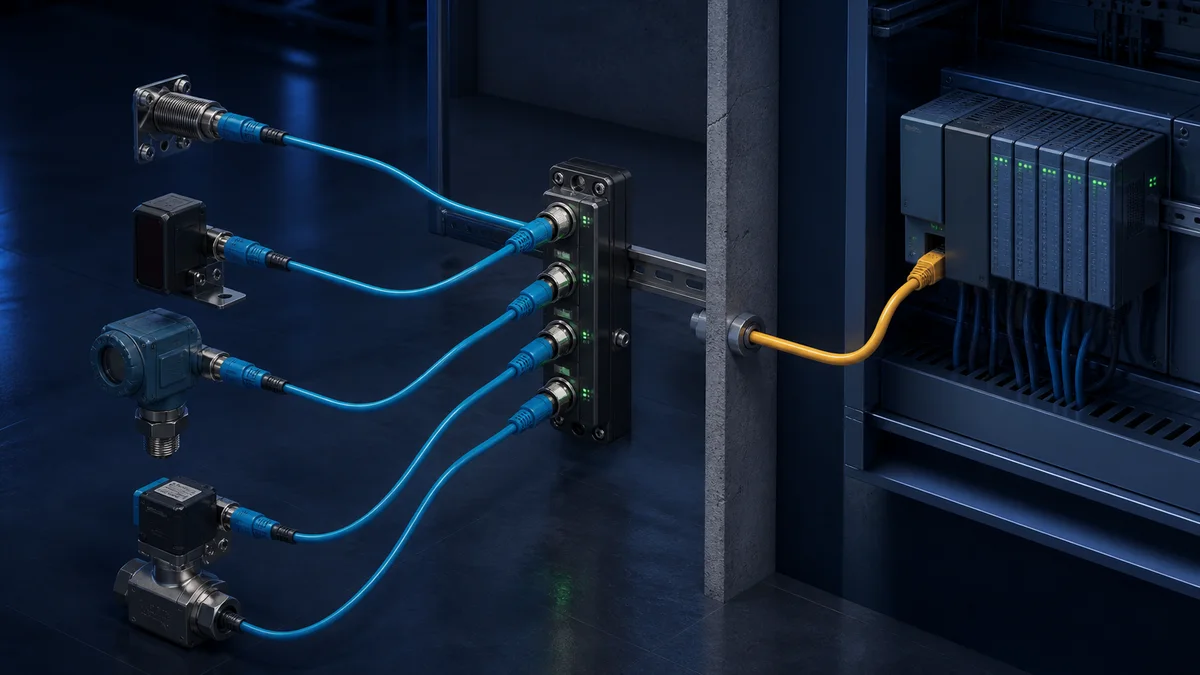
An Allen-Bradley ControlLogix or CompactLogix controller normally reaches an IO-Link sensor through an IO-Link master, not through an ordinary PLC digital input and not through the controller's Ethernet port directly. For an EtherNet/IP master, Studio 5000 configures the master as a CIP adapter/target through its supported Add-On Profile, EDS or documented generic connection. The master then owns one point-to-point IO-Link connection per port. The project must align two device descriptions: the AOP/EDS and assembly contract for the master and the IODD for each IO-Link device.
Commission in this order:
- qualify the exact Logix controller, Ethernet interface, Studio 5000 release and master catalog/firmware;
- install the master integration file from a controlled source;
- configure identity, electronic keying, IP, EtherNet/IP connection and Requested Packet Interval;
- configure each physical port's mode, class/power and exact device identity/IODD;
- allocate the master-to-PLC process-data layout;
- map raw bytes, port/device validity, events, scale and units into typed tags;
- prove controlled acyclic parameter reads/writes and data-storage authority;
- test cable loss, wrong device, master/EtherNet/IP loss, output behavior, replacement and restart.
The Rockwell ArmorBlock 5000 eight-channel IO-Link master manual is one current first-party example of this workflow. It is not a universal instruction for every Rockwell or third-party IO-Link master. Catalog, firmware, port capabilities, AOP, assembly layout, tags, parameter services and diagnostics must match the installed product.
Download the master and port contract, process-data mapping worksheet and 16-case commissioning matrix.
Separate the three systems before configuring Studio 5000
An Allen-Bradley IO-Link project contains at least three protocols/data models:
| Boundary | Roles | Configuration identity | Cyclic data | Acyclic/diagnostic path |
|---|---|---|---|---|
| Logix ↔ IO-Link master | EtherNet/IP originator/scanner ↔ adapter/target | controller/interface, master CIP Identity, AOP/EDS, keying, IP and assemblies | master input/output assemblies | CIP/profile/vendor services and master diagnostics |
| master port ↔ IO-Link device | IO-Link master port ↔ one device | port mode/class, VendorID, DeviceID, revision and IODD | device-defined process data | IO-Link index/subindex services, events and data storage |
| PLC application ↔ process | tag consumer/command owner ↔ physical sensor/actuator and process | tag contract, scale, units, validity, authority and safe behavior | typed application values | alarms, maintenance evidence and controlled parameter recipes |
A green EtherNet/IP module in the I/O tree proves neither the sensor identity nor the process-data map. A port in IO-Link OPERATE state proves neither correct engineering scaling nor acceptable process validity. Preserve evidence at each boundary.
A conventional input can use SIO, but not IO-Link features
Some IO-Link devices support Standard I/O (SIO) behavior on the C/Q line. If the sensor and circuit are electrically compatible, a standard Allen-Bradley digital input may read its conventional switching state. That gives one ordinary signal, not IO-Link identity, structured process bytes, parameters, events or automatic replacement. Choose SIO deliberately when one switch bit is the requirement; select a master when IO-Link functions are required.
Select and qualify the master
Rockwell and third parties offer master architectures that can expose IO-Link ports to Logix over EtherNet/IP. Do not select from “works with Allen-Bradley” alone. Require an exact integration path and current documentation.
| Selection gate | Required evidence | Reject or hold when |
|---|---|---|
| upstream role | EtherNet/IP adapter connection supported by exact Logix controller/interface | only Modbus TCP, PROFINET or another master variant is documented |
| Studio integration | exact AOP/EDS/generic-module workflow and compatible Studio release | download provenance or supported version is unknown |
| port capability | port count, Class A/B, current/auxiliary power, mode, connector and environmental rating | actuator power or pin assignment is inferred from another master |
| IO-Link support | specification revision, COM rates, IODD/device-validation and data-storage behavior | marketing says IO-Link but needed identity/restore behavior is absent |
| cyclic capacity | per-port input/output lengths and total EtherNet/IP assembly capacity | proposed device layout exceeds documented allocation |
| acyclic access | documented Logix/AOP/MSG/AOI or service path with concurrency limits | a generic ISDU service code is invented from another vendor example |
| diagnostics | EtherNet/IP, master, port, device/event and power evidence accessible | faults collapse into one undifferentiated status bit |
| lifecycle/security | firmware, backup/restore, product support and approved network controls | configuration cannot be reproduced or management path is uncontrolled |
The master's EtherNet/IP capacity and the devices' IO-Link timing are separate. An eight-port enclosure does not prove all eight selected devices fit the configured cyclic byte allocation, power budget, update requirement or acyclic traffic pattern.
Control AOP/EDS, IODD and online identity
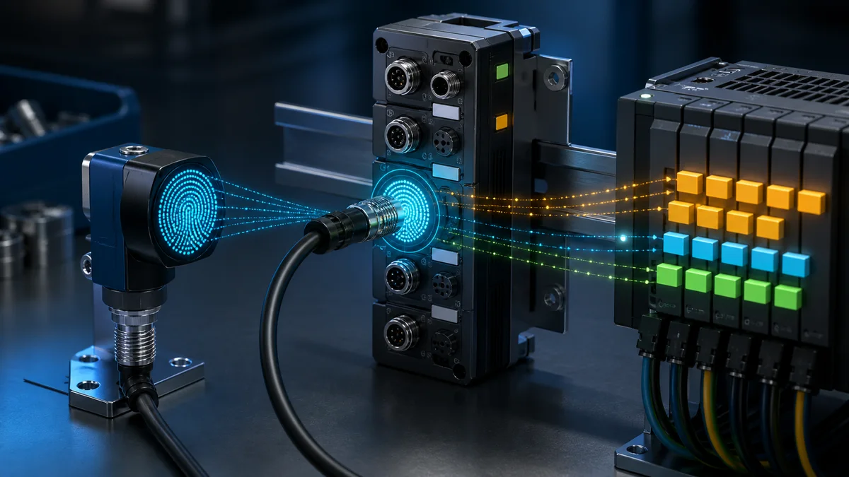
The master integration file describes the upstream EtherNet/IP adapter. The IODD describes an individual IO-Link device. Installing one does not replace the other.
| Artifact/evidence | Controls | Preserve |
|---|---|---|
| master Add-On Profile | Studio 5000 device-specific UI, generated tags and diagnostics where supported | installer, exact version, manufacturer source and compatibility record |
| master EDS | CIP identity, parameters and supported connections exposed to engineering tools | original file, hash/source and selected connection |
| generic-module contract | manual entry of assemblies, sizes, format and RPI | exact vendor connection table and byte map |
| device IODD | VendorID/DeviceID, variants, process data, parameters, events and presentation | exact filename/version/source and supported master/tool path |
| online master CIP Identity | physical vendor/product/revision and serial/MAC context | screenshot/export and electronic-keying result |
| online IO-Link identity | VendorID, DeviceID, revision and serial where exposed | port evidence and configured validation policy |
Use the manufacturer or IODDfinder for the exact IODD. A readable device label and family name do not prove variant. Some devices have process-data alternatives selected by parameter or product variant; the same nominal sensor can therefore expose a different byte length/layout.
Configure the Studio 5000 EtherNet/IP connection
Add the master through its supported profile or documented generic connection. Record:
- Logix controller and interface path;
- master CIP Identity and electronic-keying policy;
- IP allocation method, address, mask, gateway, MAC and switch/VLAN/port;
- input, output and configuration assembly instances and sizes;
- real-time format, connection type and Requested Packet Interval;
- master-generated tag layout and revision;
- connection-loss behavior and any output data sent to ports.
Do not weaken keying or pad assembly sizes until a connection opens. Compare the configured identity and directional sizes with the exact master documentation. Originator-to-Target is controller/master output data; Target-to-Originator is master/controller input data. Tool labels can invert the human words “input” and “output,” so document the producer and consumer.
Live mini-lab
Try it: press START, then STOP
A stop-dominant seal-in rung: START latches the motor output through its own contact, and STOP breaks the circuit.
Watch the output lamp: it stays on after START until you press STOP.
Free to start · runs in your browserOpens plcsimulationsoftware.com — same team
Configure each IO-Link port and its power boundary
For every port record operating mode, expected identity, validation level, device process-data variant, input/output lengths, cycle time/COM behavior exposed by the product, pin assignment, Class A/B, port current, auxiliary actuator power and data-storage policy. The master manual and device data sheet govern wiring and power.
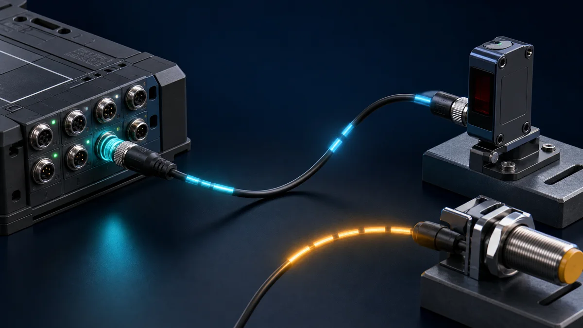
The IO-Link system description specifies a 20 m maximum master-to-device connection. Apply the exact product's permitted cable, connector, conductor size, voltage-drop, EMC and environment requirements. A short bench test does not approve a field cable or actuator power design.
| Port field | Example record | Acceptance evidence |
|---|---|---|
| mode | IO-Link, SIO input/output or disabled as supported | online port state matches approved I/O schedule |
| expected device | VendorID, DeviceID and validation rule | right device accepted; wrong controlled device rejected |
| process variant | exact IODD variant and selected mode | online length/layout matches project |
| power | port class, sensor current, auxiliary supply and fault behavior | measured supply and controlled overload/absence diagnostic |
| data storage | disabled, upload, download or product-defined policy | documented authority and replacement test |
| events | device/master event mapping and acknowledgement | induced safe event reaches correct Logix diagnostic path |
Map process data, value status and engineering meaning
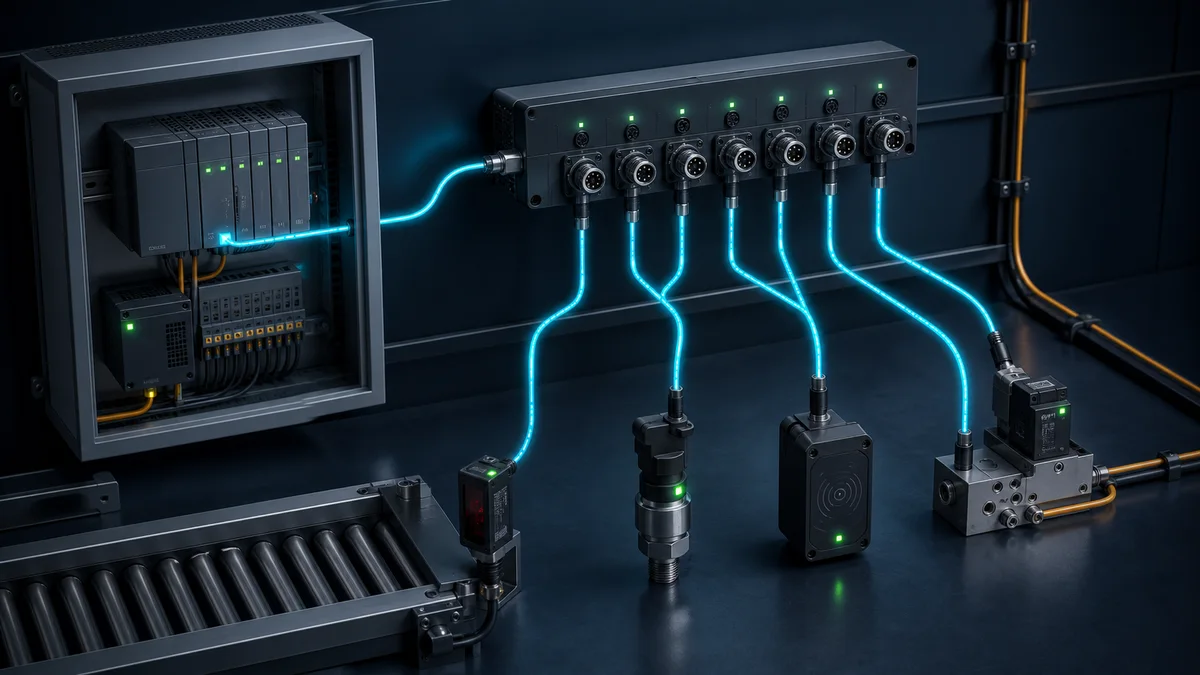
IO-Link process data is a device-defined bit/byte structure. The master then places each port's data into its own EtherNet/IP input/output assembly or generated tags. This creates two offset tables: device-within-port and port-within-master.
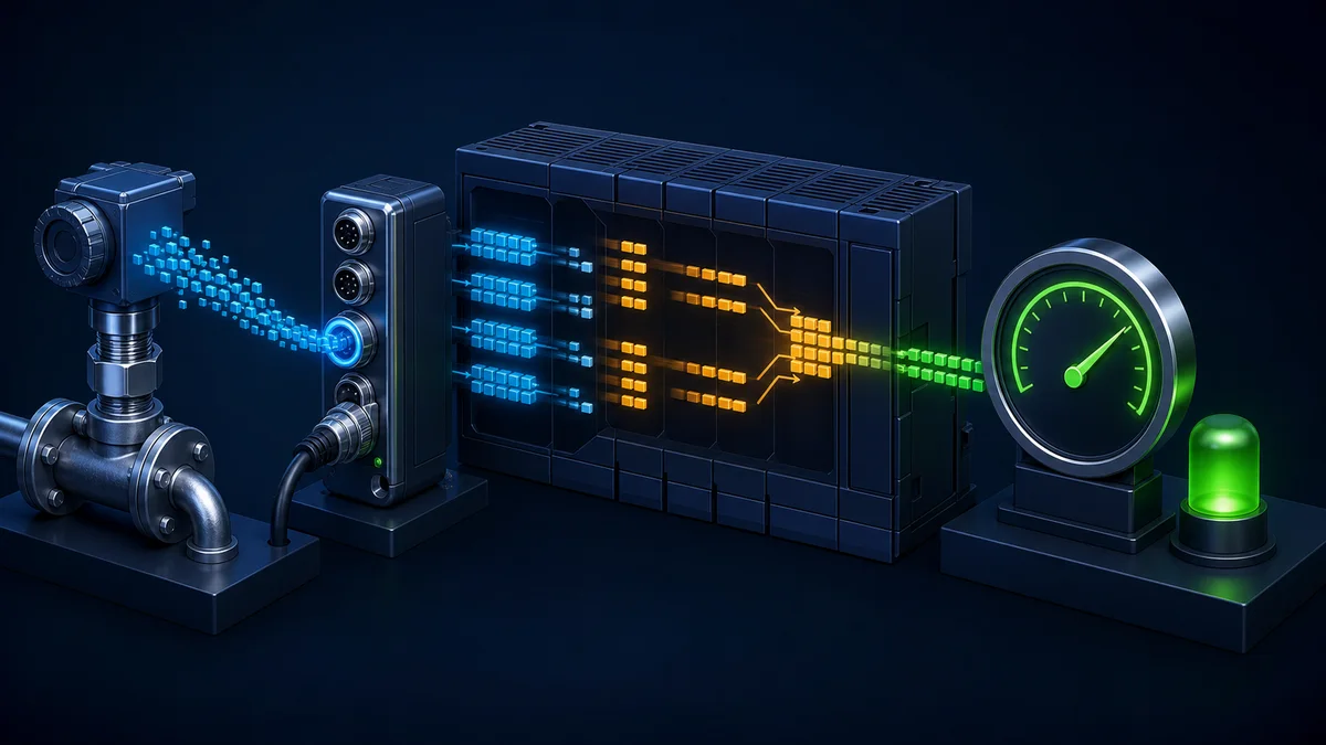
| Mapping field | Record | Proof method |
|---|---|---|
| port and direction | physical port, device input/output and master assembly direction | trace port LED/state and raw assembly |
| byte/bit offset | master tag/member or raw assembly offset plus device-internal bit | asymmetric raw patterns and controlled stimulus |
| data type | unsigned/signed integer, bitfield, float or enumeration as specified | positive, negative, limit and known hexadecimal cases |
| byte/bit order | IODD plus master integration behavior | compare exact raw bytes, not only interpreted tag |
| engineering transform | scale, offset, decimals, units and valid range | independent low/mid/high reference |
| device/value status | status bit/member, master port state and application validity | cable/device/master-loss cases |
| age | last-good timestamp and maximum consumer age | interrupt updates without clearing retained value |
| command authority | output owner, permitted state, range and acknowledgement | allowed and prohibited writes |
Do not hide device or port validity behind a default zero. A sensor can report a legitimate zero process value, while a broken cable or master fault can leave a retained zero or last value. Carry value, quality and age together.
Handle ISDU parameters and device events through the documented master path
IO-Link on-request data uses index/subindex services at the device link. The Logix-side access method is master-specific: an Add-On Profile, generated tags, Add-On Instruction, explicit CIP service, web/configuration tool or another documented mechanism may broker it. Do not copy a service/class/instance from another master.
For every writable parameter define device identity, index/subindex, type/length, permitted state, range, recipe owner, read-before value, requested value, service result, read-back value, timestamp and operator/change record. Serialize requests according to the master limits. A successful EtherNet/IP MSG only proves the master accepted or responded to that CIP transaction; verify the downstream device result and process consequence.
Events are different from cyclic process data and deliberate parameter services. Map their source, event code/type, timestamp context, acknowledgement and maintenance meaning. Prove a safe representative event rather than assuming a device warning appears automatically in a controller alarm list.
Engineer timing from sensor update to Logix task
End-to-end consumer age can include sensor measurement, device process cycle, IO-Link port/master schedule, master assembly production/RPI, EtherNet/IP delivery, Logix communication processing, controller task wait and application execution. A fast EtherNet/IP RPI cannot make a slower device update faster.
Use:
maximum consumer age ≤ device update + IO-Link/master scheduling + upstream production/delivery + Logix task/application allowance
Measure the complete path with all configured ports, devices, acyclic parameter traffic, events, other EtherNet/IP connections and representative controller load. Separate normal age, stale-data threshold and fault-recovery time.
Diagnose the first failed boundary
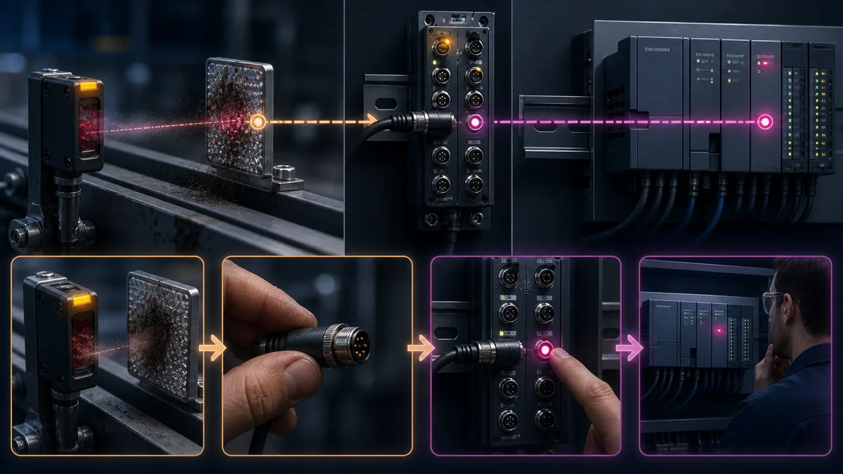
| Symptom | First evidence | Likely boundary | Do not change together |
|---|---|---|---|
| master absent in I/O tree | link/IP, CIP Identity, keying and extended connection status | EtherNet/IP/master configuration | sensor IODD and process scale |
| master connected, one port down | port mode, power/current, cable, VendorID/DeviceID and port diagnostics | device link/identity/power | upstream assemblies and RPI |
| port operates, value wrong | IODD variant, raw port bytes, master allocation and typed tag | mapping/order/scale | cable and electronic keying |
| value freezes as healthy | port/master quality, last-good timestamp and application logic | validity/age contract | replace sensor based on value only |
| parameter read fails | exact master service path, busy/error, index/subindex and device state | acyclic service/device permission | cyclic byte offsets |
| replacement communicates but behaves wrong | validation policy, data storage direction, IODD/parameter compare | identity/restore authority | blindly repeat parameter download |
| multiple ports fault together | master/auxiliary power, EtherNet/IP, assembly and master diagnostics | shared master/upstream boundary | all field cables simultaneously |
Capture the original Studio module fault/extended status, master diagnostics, port state/event, device identity, raw bytes, application quality and first process symptom before reset/reconnect overwrites the evidence.
Controlled device replacement and data storage
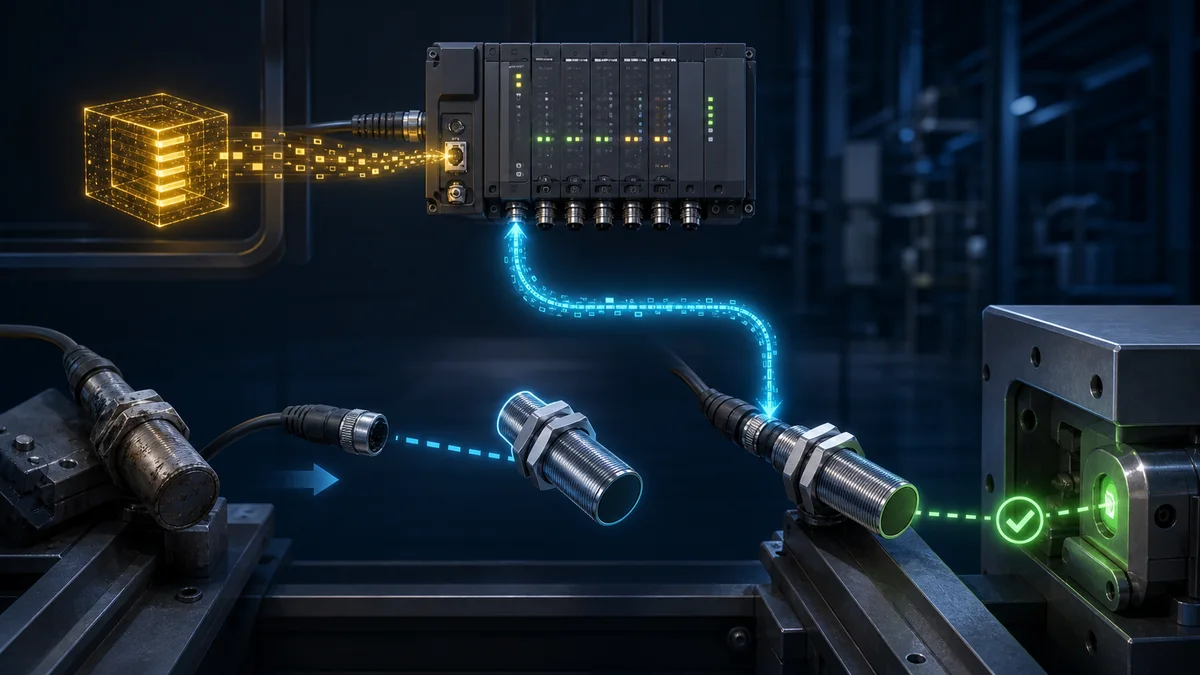
Data storage can let a compatible master retain a device parameter set and restore it to an approved replacement under configured validation rules. The direction—upload from device, download to device, or product-specific policy—must be explicit. An unauthorized field change must not silently overwrite the controlled master record.
Run three cases: approved same-device replacement, controlled wrong identity, and replacement with deliberately different parameter checksum/value. Record whether identity is accepted, which parameter set wins, how the tool reports the action, and whether the functional test passes.
Allen-Bradley IO-Link acceptance tests
| ID | Test | Method | Pass evidence |
|---|---|---|---|
| IOL01 | master baseline | archive Logix/interface, master catalog/firmware, Studio/AOP/EDS, IODDs and allocation | exact installed identities and hashes agree |
| IOL02 | EtherNet/IP identity | verify IP method, address, CIP Identity and keying | intended master connects; wrong identity is rejected |
| IOL03 | assembly contract | compare instances, directions, sizes, format and RPI | master connection succeeds only with approved contract |
| IOL04 | port mode/power | inspect every port mode, class, power and expected device | configuration matches drawings and load budget |
| IOL05 | device identity | connect intended and controlled wrong device | validation accepts/rejects exactly as designed |
| IOL06 | process-data map | stimulate asymmetric and boundary values | raw bytes, typed values, scale and units match IODD/contract |
| IOL07 | value status/age | stop device updates while retaining memory | quality becomes bad at threshold; last value is not shown as live |
| IOL08 | parameter read | read known index/subindex through documented path | type, length, value and service status match device record |
| IOL09 | parameter write | write allowed value in approved state and read back | change record, service result and functional outcome pass |
| IOL10 | blocked write | try invalid/out-of-state value | request is rejected or application prevents it as designed |
| IOL11 | device event | induce safe documented event | port/master/Logix diagnostic path and clear behavior pass |
| IOL12 | cable/device loss | interrupt one controlled port | exact fault domain, output behavior, alarm and recovery pass |
| IOL13 | master/upstream loss | interrupt master EtherNet/IP or approved power | all affected ports become invalid and process response passes |
| IOL14 | peak load | run all ports, acyclic traffic and full Logix network/task load | data age, errors and resources remain in budget |
| IOL15 | replacement/data storage | replace approved device and test wrong identity | controlled parameter authority and post-test pass |
| IOL16 | backup/restore | restore ACD, profiles, master config, IODDs and device parameters | replacement system reproduces the acceptance package |
Security and safety boundary
IO-Link parameter access can change sensing, thresholds or actuator behavior. Restrict Studio 5000, master web/configuration and CIP service paths through the approved OT architecture. Preserve AOP/EDS/IODD provenance, firmware, credentials/certificates where applicable and offline recovery. Ordinary EtherNet/IP and IO-Link do not automatically authenticate every change.
Standard IO-Link process data is not a safety function. IO-Link Safety is a distinct safety-communication extension requiring compatible products and a full safety lifecycle. A conventional IO-Link device's diagnostic bit can inform maintenance but cannot replace the safety-related sensor, logic, final element, timing, independence and validation required by the risk assessment.
Use the interactive IO-Link and industrial-protocol evidence lab to practise identity, byte mapping, parameter and replacement diagnosis. PLC Programming IO and PLC Simulation Software share an operator. The browser lab cannot validate the ACD project, Studio/AOP/EDS/IODD, controller/master/device firmware, actual assemblies, port electronics/power, field device, process or safety function.
Frequently asked questions
Does an Allen-Bradley PLC have IO-Link built in?
Do not assume so from an Ethernet or digital-I/O port. A Logix controller normally reaches IO-Link devices through a compatible master. Verify the exact controller/interface and master architecture. An ordinary input can read supported SIO switching behavior but cannot provide IO-Link identity, process frames, parameters, events or data storage.
Which IO-Link master works with ControlLogix or CompactLogix?
Select an exact master with a documented EtherNet/IP adapter integration path for the controller/interface and Studio 5000 release. Rockwell ArmorBlock 5000 is one first-party family; third-party masters can also be suitable when their certification, AOP/EDS, assembly contract and support meet the project.
How do I add an IO-Link master in Studio 5000?
Use the manufacturer's supported Add-On Profile, EDS workflow or authoritative Generic Ethernet Module contract. Configure IP, CIP Identity/keying, assemblies/sizes, format and RPI, then prove the connection before mapping devices.
Do I need an IODD in Studio 5000?
The exact workflow is master-specific. The IODD is required to describe device identity, process layout, parameters and events, but it may be imported into the master/AOP or a separate configuration tool rather than directly into Logix Designer. Preserve the file and resulting PLC map.
Is the master's EDS the same as a sensor IODD?
No. EDS describes the EtherNet/IP/CIP master for the upstream engineering system. IODD describes one IO-Link device for a master/tool. Both identities and their versions matter.
How does IO-Link process data appear in Logix tags?
The master maps each port's device-defined process bytes into an EtherNet/IP assembly or generated tag structure. Use the master allocation and IODD to locate bits/words, then apply signedness, order, scale, units, value status and age.
How do I read an IO-Link parameter from ControlLogix?
Use the exact master vendor's documented method—AOP, AOI, generated interface, MSG service or configuration tool. Record index/subindex, type, length, device state, service result and read-back. There is no universal MSG class/instance that applies to every master.
Can a Logix MSG run every scan?
No. Use a controlled trigger and one in-flight operation, wait for Done/Error, retain extended evidence and apply bounded retry/backoff. Continuous retriggering can overload the service path and hide the original failure.
How do I detect stale IO-Link data?
Combine master EtherNet/IP connection state, port/device value status and an application last-good timestamp. Mark the value bad after the approved age even if the raw tag retains its last value.
How does automatic sensor replacement work?
Where the exact master supports data storage, it can validate a replacement and transfer a stored parameter set according to configured upload/download rules. Prove which copy has authority, reject a wrong device and complete a parameter comparison and functional test.
Can one IO-Link port connect several sensors?
No. IO-Link is a point-to-point master-port/device link. A multi-port master aggregates several independent links upstream, but it does not make a multidrop IO-Link field bus.
Can IO-Link use ordinary sensor cable?
Often a specified 3-wire sensor cable is used, but verify length, conductor, connector/pinout, voltage drop, current, environment and master/device manuals. The IO-Link system description specifies a 20 m maximum between a master port and device.
Is Allen-Bradley IO-Link safe for machine safety?
Ordinary IO-Link is not a safety function. IO-Link Safety is distinct and requires compatible certified components and lifecycle validation. Keep ordinary diagnostics separate from safety-related sensing, logic and final elements.
What should I save before replacing an IO-Link device?
Save port/device identity, IODD/variant, process map, parameter set/checksum or compare, master data-storage policy, active diagnostics and a functional baseline. Then test the approved spare and a controlled mismatch.
Primary and official sources
Reviewed 31 August 2026. IO-Link sources define the device-link technology; ODVA defines the upstream EtherNet/IP/CIP context; Rockwell documentation applies only to its named products and supported revisions.
- IO-Link Interface and System Specification V1.1.4
- IO-Link Smart Sensor Profile V1.2
- IO-Link Community downloads
- IO-Link System Description
- IODDfinder
- IEC 61131-9 publication page
- IO-Link IODD specification package
- IO-Link Safety system description and specification resources
- Rockwell ArmorBlock 5000 eight-channel IO-Link master user manual 5032-UM001
- Rockwell EtherNet/IP Network Devices User Manual ENET-UM006
- Rockwell ControlLogix EtherNet/IP Network Devices User Manual 1756-UM004
- Rockwell ControlLogix System User Manual 1756-UM543
- Rockwell CompactLogix 5380 User Manual 5069-UM001
- Rockwell Logix 5000 I/O and Tag Data 1756-PM004
- Rockwell Logix 5000 Messages 1756-PM012
- ODVA EtherNet/IP Technology Overview
- ODVA Common Industrial Protocol and CIP networks
- NIST SP 800-82 Rev. 3
This guide does not approve a master/device combination, I/O map, parameter set, wiring/power design, cybersecurity architecture, functional-safety system or production change. Use the exact controller, master and device manuals, controlled AOP/EDS/IODD files, electrical drawings, machine risk assessment and witnessed acceptance record.
Now run it · free to start
Follow plant data from sensor to SCADA
Fieldbus versus Ethernet, Modbus, EtherNet/IP, PROFINET, OPC UA and MQTT, then SCADA layers and alarms, taught on simulated equipment. Free to start.
Ownership disclosure: PLC Programming IO and PLC Simulation Software are operated by the same publisher.
PLC Programming IO Editorial Team
Industrial automation education, references, and software testing
The PLC Programming IO Editorial Team publishes sourced industrial-automation education and documents how material is reviewed, tested, and corrected. A team byline means the publisher is responsible for the page; it does not represent a fictional person or imply an engineering licence.
Coverage:
- • PLC programming concepts and examples
- • Vendor software tutorials and comparisons
- • SCADA, HMI, protocols, and instrumentation
- • Training, careers, and reference material
Review standard:
- • Prefer primary and official sources
- • Record software versions when material
- • Separate tested facts from estimates
- • Publish material corrections
Important scope note
This site provides education, not project-specific engineering approval. Safety, code, and compliance decisions require a qualified person with access to the actual machine and jurisdiction.