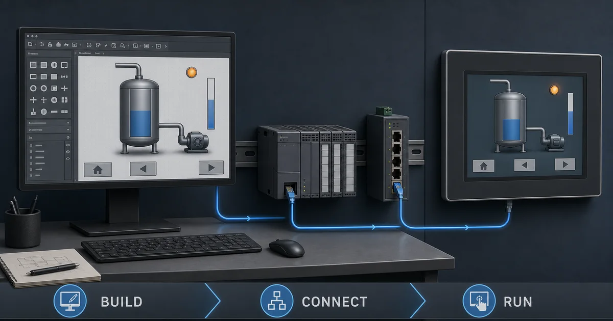
FactoryTalk View Studio Tutorial: Build Your First HMI
Master FactoryTalk View with this comprehensive tutorial covering ME vs SE, graphic development, tag databases, alarms, trends, and HMI deployment for Allen-Bradley PLCs.
FactoryTalk View Studio is the Windows-based development environment used to build FactoryTalk View HMI applications—it is the authoring tool, not the deployed runtime. Machine Edition (ME) targets machine-level applications such as supported PanelView Plus terminals; Site Edition (SE) supports station and distributed HMI/SCADA architectures. Do not assign one version number to both editions: Rockwell's public history currently lists View SE v16 and View ME v14, while installed components and target firmware still require an exact PCDC compatibility check.
FactoryTalk View Studio represents Rockwell Automation's comprehensive HMI development platform, serving as the standard interface solution for Allen-Bradley PLC systems across manufacturing, process control, and industrial automation applications worldwide. Whether you're developing a standalone machine interface or an enterprise-wide SCADA system, FactoryTalk View provides the tools needed to create professional, functional operator interfaces.
This comprehensive tutorial guides you through every aspect of FactoryTalk View development, from initial software setup through complete HMI deployment. You'll learn the fundamental differences between Machine Edition and Site Edition, master graphic development techniques, configure robust communication with Allen-Bradley PLCs, implement alarm systems, create trending displays, and deploy finished applications to hardware.
By following this step-by-step guide, you'll develop practical skills applicable to real-world HMI projects while understanding best practices that ensure maintainable, professional-quality applications. Whether you're new to HMI programming or transitioning from other platforms, this tutorial provides the foundation for successful FactoryTalk View development.
Building Allen-Bradley systems? This tutorial pairs perfectly with our Studio 5000 Programming Guide and Allen-Bradley PLC Platform Comparison for complete Logix ecosystem mastery.
Table of Contents
- Understanding FactoryTalk View Studio
- Machine Edition vs Site Edition
- Download & Licensing: The Honest Answer
- Software Installation and Setup
- Creating Your First HMI Project
- Graphic Development
- Tag Database and Communication
- Navigation and Screen Management
- Alarms and Events
- Trends and Data Logging
- Runtime and Deployment
- Best Practices
- FactoryTalk View vs FactoryTalk Optix — Which to Learn in 2026?
- Frequently Asked Questions
Understanding FactoryTalk View Studio
FactoryTalk View Studio serves as Rockwell Automation's primary human-machine interface development environment, providing comprehensive tools for creating operator interfaces for Allen-Bradley control systems. Understanding the platform's capabilities, architecture, and position within the Rockwell ecosystem is essential before beginning development.
What is FactoryTalk View?
Platform Overview: FactoryTalk View Studio is a Windows-based application development environment for creating HMI and SCADA interfaces that communicate with Allen-Bradley PLCs. The platform enables developers to design graphical screens, configure data connections, implement alarm systems, and deploy runtime applications to operator terminals or PC-based clients.
Core Capabilities:
- Graphical screen development with animation and interactivity
- Real-time data visualization from Allen-Bradley PLCs
- Alarm and event management with logging
- Historical and real-time trending
- Recipe and batch management
- Security and user access control
- Remote access and web-based visualization
- Data logging to SQL databases
Integration with Allen-Bradley Ecosystem: FactoryTalk View integrates seamlessly with the broader FactoryTalk suite and Allen-Bradley hardware:
- Studio 5000 Integration: Import tags directly from PLC programs
- FactoryTalk Linx: Unified communication for device connectivity
- FactoryTalk Historian: Enterprise-level data collection and storage
- PanelView Plus Terminals: Native deployment to Rockwell HMI hardware
- FactoryTalk Security: Centralized user authentication and authorization
- FactoryTalk Alarms and Events: Advanced alarm management capabilities
Role in Industrial Automation
Machine-Level Interface: At the machine level, FactoryTalk View provides operators with immediate visibility into equipment status, process variables, and diagnostic information. Machine Edition applications typically run on standalone PanelView Plus terminals mounted on control panels, offering touchscreen interaction for equipment operation and monitoring.
Plant-Level SCADA: Site Edition scales to plant-wide supervisory control and data acquisition systems with multiple operator stations, centralized alarm management, and comprehensive data logging. These distributed applications provide management with production metrics, quality data, and performance analytics while enabling operators to control processes across the facility.
Industry Applications: FactoryTalk View serves diverse industrial sectors:
- Automotive assembly and material handling
- Food and beverage processing lines
- Pharmaceutical batch production
- Water and wastewater treatment
- Oil and gas pipeline management
- Packaging and converting equipment
- Discrete manufacturing operations
FactoryTalk View Versions Are Edition-Specific
Current Version Status: As reviewed on 25 July 2026, Rockwell's public version history lists FactoryTalk View SE v16 and FactoryTalk View ME v14. Treat View Studio, ME runtime, SE servers and clients, FactoryTalk Linx, ViewPoint, PanelView firmware, and activation as separate compatibility rows rather than assuming a shared major version.
The official SE v16 page highlights, among other items, OKTA-based cloud identity management with MFA, new control objects, ViewPoint publishing and alarm-banner improvements, updated sizing guidance, and direct InfluxDB 3 logging. Those are SE v16 claims; they do not establish equivalent ME or terminal support.
Version Compatibility: Maintaining version compatibility across the automation ecosystem requires attention:
- Studio 5000 version compatibility for tag import
- FactoryTalk Linx version requirements
- PanelView Plus firmware compatibility
- Windows OS support requirements
- SQL Server version compatibility for data logging
Backward Compatibility: FactoryTalk View can convert supported older applications, but conversion behavior depends on the source and target versions, runtime firmware, ActiveX controls, communications, security, and deprecated features. Keep an untouched source backup, check PCDC and the release notes for the exact path, convert a copy, and run the full acceptance test before replacing a production runtime.
What Changed in Recent View SE Versions (v14 Through v16)
If you are upgrading an existing system or comparing documentation written against an older version, the following additions in recent FactoryTalk View releases are worth knowing. These are phrased conservatively because exact per-version change logs require consulting Rockwell's official release notes for your specific version.
Licensing. Licence packaging and terms vary by edition, capacity, channel, region, support entitlement, and date. Do not infer a subscription or perpetual entitlement from the installed software version; request a dated, same-scope quote and retain the activation details with the project.
Identity provider integration. Rockwell's current SE v16 page specifically names OKTA integration with MFA. Verify the supported identity provider, architecture, FactoryTalk Security components, failover behavior, and offline access in the exact release documentation rather than generalizing that statement to every OIDC provider or to ME.
InfluxDB historical logging. Rockwell lists DataLogPro/InfluxDB changes across recent SE releases, including direct InfluxDB 3 Core and Enterprise logging in v16. Confirm the supported database edition, redundancy, buffering, retention, time synchronization, migration, and licence scope for the deployed release.
Compatibility reminder. Verify the compatibility matrix in Rockwell's Product Compatibility and Download Center (PCDC) before upgrading: Studio version, FactoryTalk Linx version, PanelView Plus firmware, and Windows version must be a supported combination. Save the dated matrix and tested combination with the project record.
Machine Edition vs Site Edition
Selecting between FactoryTalk View Machine Edition (ME) and Site Edition (SE) represents a critical early decision that fundamentally impacts project architecture, licensing costs, and system capabilities. For the full ME-vs-SE breakdown — architecture, licensing, and which to pick — see FactoryTalk View ME vs SE. Understanding the distinct characteristics, capabilities, and ideal applications for each edition ensures appropriate platform selection.
Machine Edition (ME) Overview
Architecture: Machine Edition implements a standalone architecture where the HMI application runs locally on a single operator terminal or industrial PC. All configuration, graphics, logic, tags, and alarms exist within a self-contained development file (.MED); the compiled .mer runtime file is what actually deploys to target hardware without requiring server infrastructure.
Deployment Model: ME applications deploy directly to:
- PanelView Plus 7 operator terminals (4-15 inch displays)
- PanelView Plus 6 terminals (legacy, still widely deployed)
- Industrial PCs with FactoryTalk View ME Station runtime
- VersaView industrial monitors with integrated runtime
- Embedded operator interfaces in control panels
Ideal Applications: Machine Edition excels in scenarios requiring:
- Standalone machine control interfaces
- Equipment-mounted operator terminals
- Self-contained skid or modular systems
- Original equipment manufacturer (OEM) machinery
- Applications with single operator station requirements
- Systems requiring no centralized data collection
Technical Characteristics:
- Single application instance per terminal
- Local alarm management without central logging
- Controller communication through the configured FactoryTalk Linx or supported communication path
- No distributed architecture or redundancy
- Limited to single display station per application
Site Edition (SE) Overview
Architecture: Site Edition implements a distributed client-server architecture with separate server components managing data, alarms, and communications while multiple client stations provide operator interface access. This architecture enables plant-wide systems with centralized data management and distributed operator access.
Deployment Model: SE applications deploy across multiple components:
- Server: Windows PC/server running data, alarm, and network management services
- Clients: Multiple operator stations connecting to central servers
- Web Clients: Browser-based access via thin-client technology
- Remote Access: VPN or secure remote desktop connections
Ideal Applications: Site Edition addresses requirements including:
- Plant-wide SCADA systems with multiple operator stations
- Centralized alarm and event management
- Historical data collection to SQL databases
- Multiple simultaneous operators viewing different screens
- Redundant server configurations for high availability
- Remote access from engineering offices or management
- Enterprise integration with MES/ERP systems
Technical Characteristics:
- Distributed architecture with server/client separation
- Centralized data, alarm, event, and communication services selected for the application
- Client and server capacity governed by the purchased activation, release, architecture, and tested workload
- Redundancy options available for supported components and configurations
Feature Comparison Table
| Feature | Machine Edition (ME) | Site Edition (SE) |
|---|---|---|
| Architecture | Standalone application | Distributed client/server |
| Operator scope | One machine-level runtime | One or more clients within a supported SE architecture |
| Alarm management | Runtime-local application scope | Centralized services can be designed across the application |
| Data logging | Local machine-oriented logging options | Server-oriented historical logging and integration options |
| Redundancy | Not a distributed-server architecture | Supported server redundancy options require exact design validation |
| Capacity | Verify terminal, runtime, display, and tag limits for the selected release | Verify edition, activation, server, client, and workload limits |
| Security | Application and platform controls for the terminal | FactoryTalk Security can be used across the distributed system |
| Remote access | Depends on the selected terminal and approved remote-support design | Depends on the selected client technology and approved architecture |
| Network Distribution | Single device | Distributed across network |
| PLC connectivity | Configured communication path for the machine runtime | Central or distributed data-server design |
| Scripting and extensibility | Confirm supported ME functions for the release and target | Confirm supported SE client/server functions for the release |
Licensing Differences
Do not budget either edition from an undated web price. FactoryTalk View is sold in different editions, activation arrangements, capacities, and regional channels. Build a same-scope licence worksheet containing:
- FactoryTalk View Studio development edition and activation type;
- ME terminal runtime or ME Station requirement;
- SE application servers, data servers, alarm services, and operator clients;
- FactoryTalk Linx, historian, thin-client, redundancy, or other required options;
- Windows, SQL Server, virtualization, backup, and support requirements;
- application tag/display scope, concurrent users, and future expansion;
- subscription or perpetual term, support entitlement, currency, tax, and quote expiry.
Request a dated Rockwell or authorised-distributor quote for that worksheet. A bare development seat and a distributed redundant application are not comparable scopes.
When to Use Each Edition
Choose Machine Edition When:
- Project involves single operator station
- Budget constraints require cost-effective solution
- Application is standalone machine or equipment
- No centralized data collection required
- Simple alarm logging meets requirements
- OEM equipment requiring embedded HMI
- Maintenance simplicity is prioritized
- Limited IT infrastructure available
Choose Site Edition When:
- Multiple operator stations required
- Centralized alarm management essential
- Historical data logging to SQL database needed
- System requires redundancy for availability
- Remote access from offices or mobile devices required
- Integration with enterprise systems (MES/ERP)
- Regulatory requirements mandate audit trails
- Plant-wide visibility across processes needed
Migration Path: Treat an ME-to-SE move as a tested migration, not an automatic conversion promise. Inventory displays, global objects, parameters, alarms, tags, communications, macros, recipes, security, and terminal-specific behavior. Convert a representative slice, document unsupported items, and execute the same operator acceptance tests on both systems before estimating the remaining work.
ME vs SE in One Place
A condensed reference for teams comparing the two editions before committing to a project architecture.
| Decision point | Machine Edition (ME) | Site Edition (SE) |
|---|---|---|
| Primary target hardware | PanelView Plus terminals | Windows PCs / servers |
| Compiled runtime file | .mer (deployed via Transfer Utility) |
No single compiled file; runs as services |
| Studio 5000 integration | Native tag browse | Native tag browse via Data Server |
| Operator stations | One runtime instance for the machine application | Governed by the selected SE architecture, licences, and tested capacity |
| Legacy migration | Inventory and test any source application | Use Rockwell's release-specific migration guidance and validate converted objects |
| Typical project type | OEM machine, standalone skid | Plant SCADA, multi-line factory |
| Redundancy | Not supported | Server redundancy available |
For the full architecture deep-dive — including which license SKUs to quote — see the dedicated FactoryTalk View ME vs SE comparison.
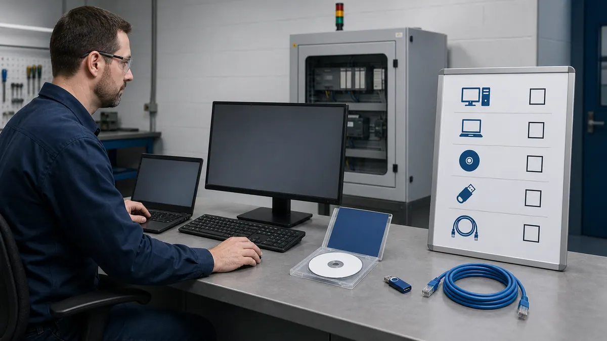
Download & Licensing: The Honest Answer
One of the first questions beginners ask is whether FactoryTalk View Studio is free to download or try. Here is the straight answer.
Where to download. FactoryTalk View Studio is downloaded from Rockwell Automation's Product Compatibility and Download Center (PCDC) at compatibility.rockwellautomation.com. You must create and log in with a registered Rockwell Automation account to access the download files — the files are not publicly distributed without account authentication.
Is it free? No. FactoryTalk View Studio requires a purchased license activated through Rockwell's FactoryTalk Activation Manager. Without a valid license the software will not operate in a production-capable state. A time-limited evaluation may be available through Rockwell Automation or an authorized distributor — check with your local Rockwell distributor for current evaluation options, as availability and duration vary by region and agreement.
Licensing overview.
- Quote the exact ME or SE development edition needed by the project.
- Confirm the activation method, transfer procedure, and whether a hardware terminal or PC runtime carries a separate entitlement.
- Include every required server, client, communication, historian, thin-client, and redundancy component.
- Record subscription or perpetual term, support entitlement, region, and quote expiry.
Offline activation. For an isolated engineering workstation, use the offline activation workflow documented for the installed FactoryTalk Activation Manager release. Test activation backup and recovery before the workstation is needed during an outage.
Procurement tip. Rockwell Automation sells through a distributor network (Rockwell, Mouser, authorized SIs). Pricing is not publicly listed and varies by region and contract tier. Contact your local Rockwell distributor for current pricing and evaluation program details.
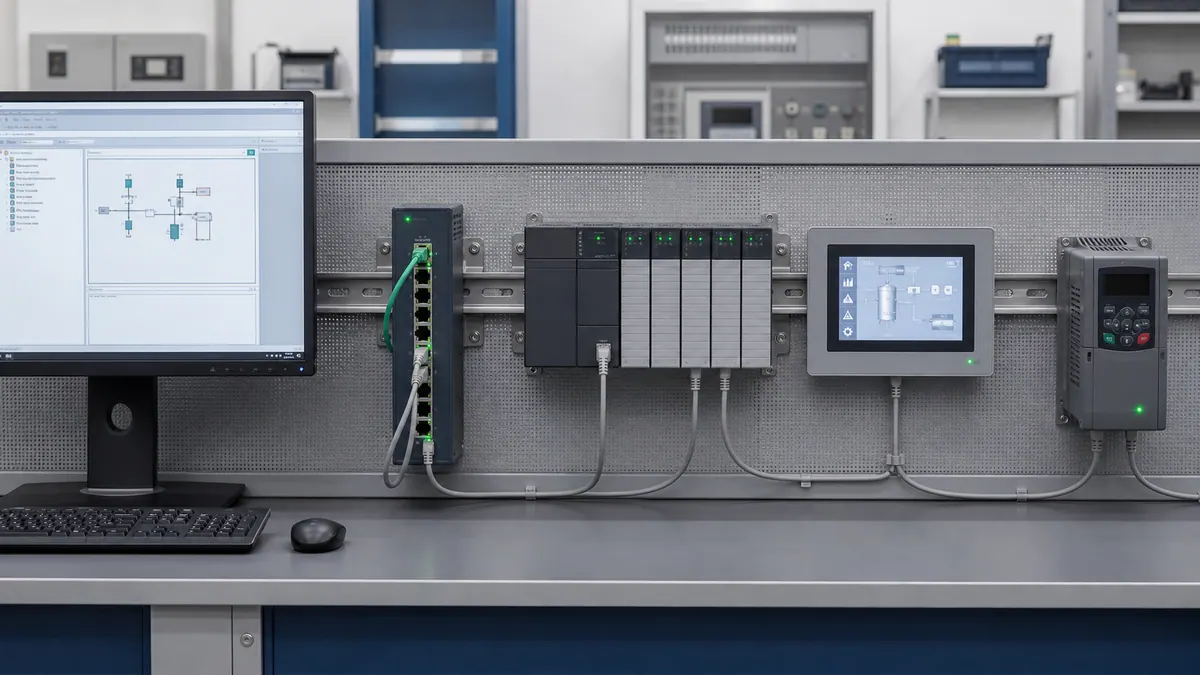
Software Installation and Setup
Proper installation and configuration of FactoryTalk View Studio, communication software, and supporting components establishes the foundation for successful HMI development. This section guides you through the complete setup process from system requirements through first project creation.
System Requirements
Do not use a generic processor, RAM, storage, Windows, or SQL list for FactoryTalk View. Rockwell publishes release- and architecture-specific requirements and updated SE sizing guidance. Before installation, save a dated compatibility record containing:
- View Studio edition, version, patch and activation;
- operating-system edition, build and virtualization status;
- ME target terminal and firmware, or every SE server/client role;
- FactoryTalk Services Platform, Linx, ViewPoint, Historian, SQL/InfluxDB, ThinManager and other companion versions actually used;
- CPU, memory, storage, display and network sizing for the measured application workload;
- required Windows roles, domain/identity design, security software exceptions approved by the site, and backup method.
Use PCDC and the release notes as the source of truth. A workstation that can edit a small ME application is not evidence that it is sized or supported for a distributed SE system.
Installation Process
Step 1: Pre-Installation Preparation Before installing FactoryTalk View Studio, ensure system readiness:
- Compatibility record: Confirm the supported Windows build, required components, target firmware and exact install order in PCDC and the release notes.
- Change control and backup: Back up the workstation or server and the application, record rollback steps, and use an approved maintenance window.
- Security controls: Keep endpoint protection and firewall policy under site control. Apply only vendor-documented, security-approved exclusions; do not disable protection as a generic installation step.
- Privileges: Use the approved installation account and remove unnecessary elevated access after setup.
- Coexistence: Inventory installed FactoryTalk and Studio components before changing them. Do not uninstall another version until the supported migration/coexistence path and rollback are documented.
Step 2: Product Downloads Obtain software from Rockwell Automation:
- Visit Product Compatibility and Download Center (PCDC) at compatibility.rockwellautomation.com
- Log in with a registered Rockwell Automation account (required to access downloads)
- Navigate to FactoryTalk View Studio section
- Select the supported release for the exact product and architecture (the public history currently lists SE v16 and ME v14)
- Download FactoryTalk Linx communication software
- Download activation files if using pre-purchased licenses
Step 3: FactoryTalk View Installation Execute installation following this sequence:
- Right-click installer and select "Run as administrator"
- Accept license agreement and select installation path
- Choose installation type:
- Machine Edition Only: For standalone HMI development
- Site Edition Only: For distributed SCADA development
- Both Editions: Complete development capabilities
- Select additional components:
- FactoryTalk Activation Client (required)
- FactoryTalk View Studio documentation
- Sample applications (recommended for learning)
- Complete installation and restart when prompted
Step 4: FactoryTalk Linx Installation Communication software installation:
- Run FactoryTalk Linx installer as administrator
- Accept license and select installation directory
- Choose communication driver components:
- AB_ETHIP-1: Ethernet/IP driver (required for Allen-Bradley PLCs)
- AB_KT-1: Legacy DH-485/DH+ drivers (if needed)
- AB_VIRTUAL-1: Simulation driver for offline development
- Complete installation and restart communication services
Installation Verification: Confirm successful installation:
- Launch FactoryTalk View Studio from Start menu
- Verify activation status in Help → About menu
- Confirm FactoryTalk Linx Gateway running in system services
- Test connectivity with RSLinx Classic Enterprise or FactoryTalk Linx
License Activation
FactoryTalk Activation Manager: Rockwell uses FactoryTalk Activation for license management:
Activation Types:
- Computer-Locked: License tied to specific PC hardware
- Dongle: USB hardware key with transferable license
- Portable: Move license between computers via rehost process
- Server: Network-based floating license server
Activation Process:
- Launch FactoryTalk Activation Manager from Start menu
- Select "Activate Software" wizard
- Choose activation method:
- Online: Direct internet activation (fastest)
- Phone: Call Rockwell for activation codes
- File-Based: Transfer activation files via email
- Enter serial number and product key from purchase
- Complete activation and verify licensed products appear green
- Test activation by launching FactoryTalk View Studio
Troubleshooting Activation Issues:
- Ensure Windows date/time set correctly
- Verify internet connectivity for online activation
- Check firewall settings allowing activation service
- Confirm administrator privileges during activation
- Contact Rockwell Technical Support for persistent issues
Communication Setup
FactoryTalk Linx Configuration: Configure communication paths to Allen-Bradley PLCs:
Step 1: Network Adapter Configuration
- Configure PC Ethernet adapter with static IP on PLC network subnet
- Example: PC = 192.168.1.100, PLC = 192.168.1.10, Subnet = 255.255.255.0
- Disable unnecessary network adapters to avoid routing conflicts
- Configure Windows Firewall to allow FactoryTalk communication
Step 2: Device Discovery
- Launch FactoryTalk Linx Gateway from system tray
- Open RSLinx Enterprise or Linx configuration tool
- Browse network tree to discover Allen-Bradley devices
- Verify PLC appears in device list with IP address
- Test communication by reading PLC properties
Step 3: Shortcut Creation Create communication shortcuts for HMI tag references:
- Right-click discovered PLC in RSLinx
- Select "Create Shortcut" and provide descriptive name
- Shortcut format:
Shortcut_Name,PLC_Name,Program:Tag_Name - Example:
Line1_PLC,CompactLogix,MainProgram:Motor_Run
Communication Testing: Verify successful PLC communication:
- Use RSLinx diagnostic tools to read PLC tags
- Measure source update, network transfer, HMI data age, and display refresh against the task requirement
- Test communication under various conditions
- Document communication paths for HMI configuration
Setup Workflow and the Communication Shortcut
If Studio cannot browse or resolve controller tags, verify the FactoryTalk Linx communication shortcut early. The same symptom can also come from network, compatibility, controller-path, permissions, or project configuration faults, so use the diagnostics rather than assuming one cause.
Correct setup sequence:
- Install FactoryTalk View Studio and FactoryTalk Linx in the correct order (Linx first is generally recommended — check the release notes for your version).
- Configure your PC's Ethernet adapter with a static IP on the same subnet as the PLC (e.g., PLC at 192.168.1.10, PC at 192.168.1.100, mask 255.255.255.0).
- Open FactoryTalk Linx / RSLinx Enterprise and create a communication shortcut to the PLC. This is the step most beginners skip. Without a named shortcut, FactoryTalk View Studio cannot browse or resolve PLC tags — they simply will not appear in the tag browser. The shortcut name becomes part of every tag address you write.
- Verify the shortcut works by reading a known PLC tag via the RSLinx diagnostic tools before opening Studio.
- In FactoryTalk View Studio, open the tag editor and use the tag browser — you should now see the PLC's tag structure under the shortcut name.
- Import or manually create HMI tags pointing to PLC addresses via the shortcut.
- Build your first display, compile the
.merfile, and use the Transfer Utility to send it to the PanelView Plus (see the deployment section below).
Key takeaway: If tags are not browsing in Studio, check the shortcut before anything else. This accounts for the majority of "it's not working" posts on automation forums.
Creating Your First HMI Project
Developing your first FactoryTalk View application teaches fundamental concepts applicable to all HMI projects. This section walks through creating a simple machine interface from project creation through basic operator screens.
Download the worked-example worksheets: use the first-HMI tag map CSV to define the six controller/HMI interfaces used below, then record the result in the eight-test acceptance checklist CSV. These are vendor-neutral planning and test worksheets, not import-ready FactoryTalk project archives; review every address and safety behavior against your controller program.
Project Creation
Starting a New Project:
Step 1: Launch Studio
- Open FactoryTalk View Studio (Machine Edition or Site Edition)
- Select "Create a new application" from splash screen
- Choose appropriate edition for your project requirements
Step 2: Application Setup Wizard The wizard guides initial project configuration:
Machine Edition Setup:
- Application Name: Enter descriptive name (example: "Conveyor_HMI")
- Location: Select project storage directory
- Display Settings: Configure primary display
- Resolution: Match target PanelView or PC (e.g., 1024x768)
- Color Depth: 16-bit or 32-bit color
- Orientation: Landscape or portrait
- Communication: Select communication type (configured later)
- Security: Enable if user access control required
- Startup: Configure startup display and behavior
Site Edition Setup:
- Application Name: Enter descriptive name
- Network Configuration: Define server components
- Data Server: Manages tag communication
- Alarm Server: Handles alarm processing
- Network Station: Provides operator interface
- Display Configuration: Set screen resolution for clients
- Database Configuration: SQL Server for alarm/data logging
- Security Integration: FactoryTalk Security setup
Step 3: Initial Project Structure Studio creates default project structure:
- Graphics folder: Display files (.gfx)
- Tags folder: Tag database configuration
- Macros folder: VBA code modules
- Parameters folder: Global parameters
- Alarms folder: Alarm configuration (SE)
- Data Log Models: Data logging configuration (SE)
Display Configuration
Creating Display Files: Displays represent individual screens in the HMI application:
Step 1: Create New Display
- Right-click Graphics folder in Explorer window
- Select "New Display"
- Enter display name (example: "Main_Overview")
- Set display dimensions matching project configuration
- Choose base display type:
- Normal: Standard operator screen
- Popup: Dialog overlay screen
- Replace: Full-screen replacement
- Global Object: Reusable display component
Step 2: Display Properties Configure display characteristics:
- Background Color: Set consistent color scheme
- Update Rate: Screen refresh interval (500ms typical)
- Cache Mode: Memory management for performance
- Startup Script: VBA code executing on display load
- Security: User access requirements
Step 3: Grid and Alignment Settings Configure development aids:
- Select Tools → Options → Display tab
- Enable grid display for object alignment
- Set grid spacing (10 pixels recommended)
- Enable snap-to-grid for consistent spacing
- Configure rulers and guides
Communication Setup with PLC
Tag Integration from Studio 5000: Import tags directly from PLC program for consistency:
Step 1: Export Tags from Studio 5000
- Open PLC program in Studio 5000 Logix Designer
- Right-click Controller Tags folder
- Select "Export Tags"
- Choose CSV format and save to known location
- Include External Access property in export
Step 2: Import Tags to FactoryTalk View
- In FactoryTalk View Studio, select Tags folder
- Choose "Import Tags" from toolbar
- Select CSV file exported from Studio 5000
- Map columns to FactoryTalk View tag properties:
- Tag Name → Name
- Data Type → Type
- Scope → Address configuration
- Complete import and verify tags appear in database
Manual Tag Creation: Alternatively, create tags manually for complete control:
Step 3: Create Manual Tags
- Open Tag Editor (Machine Edition) or HMI Tags (Site Edition)
- Click "New" to create tag
- Configure tag properties:
- Name: Descriptive identifier (e.g., "Conveyor_Motor_Run")
- Type: Data type (Analog, Digital, String)
- Address: PLC connection reference
- Alarm: Enable if alarming required
- Log: Enable for data logging
- Security: Access control settings
Tag Addressing Format: Create PLC tag connections using proper syntax:
Machine Edition Address Format:
{Communication_Path}Tag_Name
Example: {[AB_ETHIP-1]CompactLogix,2,MainProgram:Conveyor.Motor_Running}
Site Edition Address Format:
ServerName::PLCName,Program:Tag_Name
Example: DataServer::Line1_PLC,MainProgram:Conveyor.Motor_Running
Building a Simple Screen
Create a Basic Overview Screen:
Step 1: Add Static Graphics Create visual context with static graphics:
- Open Main_Overview display
- Use drawing tools to create background:
- Rectangle Tool: Draw equipment outlines
- Line Tool: Add piping or connections
- Text Tool: Add labels and titles
- Add company logo and screen title
- Create legend for colors and symbols
- Add navigation buttons (configured later)
Step 2: Add Dynamic Objects Incorporate live data visualization:
Push Buttons:
- Select Push Button object from toolbox
- Place on display at desired location
- Configure button properties:
- Caption: Display text (e.g., "START")
- Press Action: Write value to PLC tag
- Connection: Tag address for button state
- Set appearance for pressed/unpressed states
Indicators:
- Add Multi-State Indicator object
- Connect to PLC Boolean tag
- Configure states:
- State 0: Motor stopped (gray color)
- State 1: Motor running (green color)
- Add text labels showing current state
Numeric Displays:
- Insert Numeric Display object
- Connect to PLC analog tag
- Configure properties:
- Format: Decimal places and units
- High/Low Limits: Range validation
- Color Thresholds: Value-based coloring
- Add engineering units label
Step 3: Test Display in Runtime Validate functionality before full development:
- Save all changes to display
- Launch Runtime application
- Test buttons trigger PLC actions
- Verify indicators update with PLC status
- Confirm numeric values display correctly
This simple screen demonstrates core FactoryTalk View concepts applicable to complex applications. Subsequent sections expand these fundamentals with advanced features and techniques.
Graphic Development
Professional graphic development distinguishes functional HMI applications from exceptional user interfaces. This section explores advanced techniques for creating intuitive, visually appealing, and highly functional operator screens using FactoryTalk View's comprehensive graphics capabilities.
Drawing Tools and Objects
Basic Drawing Objects: FactoryTalk View provides fundamental drawing tools for creating custom graphics:
Rectangle and Rounded Rectangle:
- Create equipment outlines, backgrounds, and containers
- Configure fill colors, border styles, and corner radius
- Use for tanks, hoppers, panels, and enclosures
- Apply gradients for 3D depth perception
Ellipse and Circle:
- Draw motors, pumps, vessels, and circular equipment
- Perfect circles using Shift key while drawing
- Combine multiple ellipses for complex equipment representations
- Use for gauges, indicators, and rotating equipment
Line and Polyline:
- Represent piping, electrical connections, and material flow
- Configure line width, style (solid, dashed, dotted), and color
- Arrow endpoints show flow direction
- Polyline for complex paths with multiple segments
Polygon:
- Create custom shapes for specialized equipment
- Fill patterns and gradient options
- Use for valves, dampers, and irregular equipment
- Combine with other objects for complex graphics
Text Objects:
- Static labels, titles, and instructions
- Dynamic text displaying tag values
- Configurable fonts, sizes, colors, and alignment
- Text rotation for vertical labels and tight spaces
Object Manipulation: Essential editing capabilities:
- Alignment Tools: Distribute and align multiple objects
- Grouping: Combine objects for unified manipulation
- Layering: Send to back/bring to front for proper overlapping
- Rotation: Rotate objects to match physical orientation
- Sizing: Precise dimension control with property editor
- Copying: Duplicate consistent elements efficiently
Symbol Factory and Graphics Libraries
Integrated Symbol Libraries: FactoryTalk View includes extensive pre-built graphic libraries:
Symbol Factory: An industrial graphics library whose installed content depends on the FactoryTalk View edition and version:
- Motors: Various motor types with rotation animation
- Valves: Gate, globe, ball, butterfly valves with position
- Pumps: Centrifugal, positive displacement, vacuum
- Tanks: Process vessels, storage tanks, hoppers
- Conveyors: Belt, roller, chain conveyors with animation
- Instruments: Gauges, transmitters, analyzers
- Electrical: Switches, breakers, indicators
Using Symbol Factory:
- Select Symbol Factory icon from toolbar
- Browse categories to find appropriate symbol
- Select symbol and place on display
- Resize maintaining aspect ratio
- Configure animation connections to PLC tags
Custom Graphics Import: Import external graphics for specialized equipment:
Supported Formats:
- Bitmap: BMP, JPG, PNG for photorealistic graphics
- Vector: EMF, WMF for scalable graphics
- CAD Files: Import from AutoCAD or SolidWorks
- 3D Graphics: Pre-rendered 3D equipment views
Import Process:
- Prepare graphics in external tool (AutoCAD, Visio, etc.)
- Export to compatible format
- Import to FactoryTalk View via Insert → Bitmap/Metafile
- Scale and position on display
- Add animation connections for dynamic behavior
Animation Techniques
Color Animation: Change object colors based on tag values for status indication:
Configuration:
- Select object for animation
- Right-click and choose "Animations"
- Select "Color" animation type
- Choose fill or line color
- Configure color states:
- Expression: Tag reference or calculation
- Thresholds: Value ranges for color changes
- Colors: Assigned to each range
- Example: Tank level color (blue = low, yellow = medium, red = high)
Visibility Animation: Show/hide objects based on conditions for cleaner displays:
Configuration:
- Select object for visibility control
- Open Animations dialog
- Choose "Visibility" animation
- Configure expression determining visibility
- Set visible/invisible states based on tag value
- Use for alarm indicators, conditional prompts, mode-dependent controls
Position Animation: Move objects to represent physical motion:
Horizontal/Vertical Sliders:
- Create slider graphic (rectangle or custom shape)
- Configure horizontal or vertical position animation
- Set expression tag representing position
- Define minimum/maximum positions on screen
- Map tag range to screen coordinates
- Example: Valve stem position, cylinder extension
Rotation Animation: Rotate objects for rotating equipment representation:
Configuration:
- Select rotating object (motor, fan, agitator)
- Configure "Rotation" animation
- Set rotation center point
- Link to speed or status tag
- Configure rotation direction and speed
- Example: Motor shaft, fan blades, mixing impeller
Size Animation: Scale objects dynamically for level or pressure representation:
Configuration:
- Create scalable graphic (typically rectangle)
- Configure "Width" or "Height" animation
- Link to analog tag (level, pressure, flow)
- Set minimum and maximum sizes
- Map tag range to size range
- Use for tank levels, bar graphs, trend indicators
Touch-Sensitive Objects
Push Buttons: Primary operator interaction method for discrete control:
Button Types:
- Momentary: Active only while pressed
- Maintained: Toggle on/off with each press
- Set/Reset: Separate buttons for on/off control
Configuration:
- Place Push Button object on display
- Set button caption and appearance
- Configure press action:
- Set Tag: Write value to PLC tag on press
- Toggle Tag: Invert Boolean tag state
- Momentary: Set while pressed, reset on release
- Add release action if needed
- Configure visual feedback (color change, border)
- Add confirmation prompts for critical actions
Numeric Input: Enable operator entry of setpoints and parameters:
Configuration:
- Place Numeric Input object
- Link to PLC tag receiving value
- Configure input properties:
- Minimum/Maximum: Valid range limits
- Decimal Places: Precision control
- Security: User authorization requirement
- Keypad Type: Full numeric or limited
- Add input validation and error handling
- Provide visual feedback on successful entry
String Input: Accept text entry for recipes, product names, operator notes:
Configuration:
- Insert String Input object
- Connect to PLC string tag or database field
- Set maximum length and allowed characters
- Configure input keyboard (full QWERTY or limited)
- Add validation for format requirements
- Implement confirmation for critical text entry
Multi-State Selectors: Provide discrete state selection with visual feedback:
Configuration:
- Place List Selector or Radio Button object
- Define available states:
- State 0: AUTO mode
- State 1: MANUAL mode
- State 2: OFF mode
- Link to PLC mode selection tag
- Configure visual appearance for each state
- Add security restrictions for mode changes
- Include confirmation for safety-critical mode selections
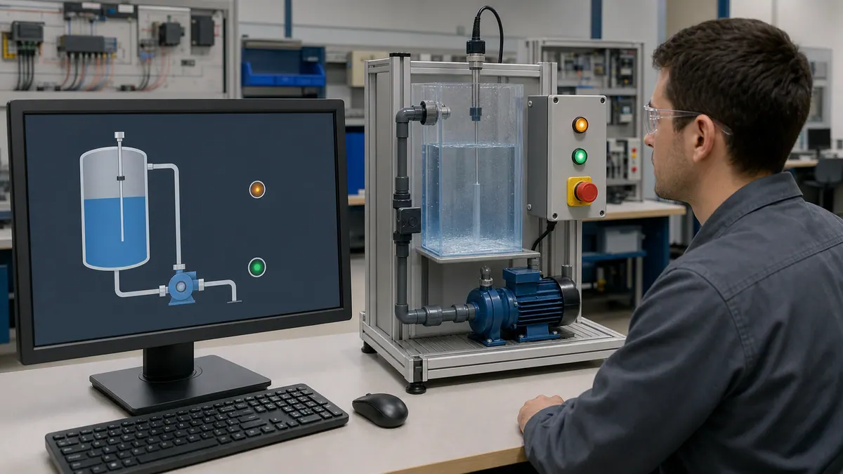
Example: Animated Tank Level Display
Complete Tank Level Graphic with Animation:
Step 1: Create Tank Structure
- Draw tank outline using rectangle (300x400 pixels)
- Add tank label text object: "Product Tank T-101"
- Draw level indicator rectangle inside tank (280x380 pixels)
- Add high/low level markers with lines and text
Step 2: Configure Level Animation
- Select level indicator rectangle
- Open Animations dialog → Height
- Configure expression:
Tank_T101.Level_PV - Set minimum height: 0 pixels (empty)
- Set maximum height: 380 pixels (full)
- Map PLC tag range (0-100%) to pixel range
Step 3: Add Color Animation
- Select level indicator (same rectangle)
- Add Color animation → Fill Color
- Configure thresholds:
- 0-25%: Red (low level alarm)
- 25-75%: Green (normal operation)
- 75-100%: Yellow (high level warning)
- Apply color states based on level value
Step 4: Add Level Value Display
- Place Numeric Display object above tank
- Connect to
Tank_T101.Level_PVtag - Format: 1 decimal place with "%" suffix
- Set font size and color for visibility
Step 5: Add Control Buttons
- Place "Fill" push button below tank
- Configure to set
Tank_T101.Fill_Valve_CMD= 1 on press - Place "Drain" push button
- Configure to set
Tank_T101.Drain_Valve_CMD= 1 on press - Add "Stop" button to reset both commands to 0
Result: Professional animated tank graphic with:
- Dynamic level indication rising/falling with actual process
- Color-coded level ranges for operator awareness
- Precise numeric value display
- Operator control interface
- Reusable template for additional tanks
This approach applies to motors, conveyors, valves, and all equipment types, creating intuitive operator interfaces that accurately represent physical processes.
Tag Database and Communication
Effective tag management and PLC communication configuration form the foundation of reliable HMI operation. This section covers comprehensive tag database organization, communication setup, and data handling strategies for robust FactoryTalk View applications.
HMI Tags vs PLC Tags
Understanding Tag Relationships:
PLC Tags: Tags residing in Allen-Bradley PLC programs represent physical I/O, internal logic variables, and control parameters. PLC tags are created and managed in Studio 5000 Logix Designer with specific data types, scope, and external access properties.
HMI Tags: Tags in FactoryTalk View provide interface points to PLC data, local calculations, and temporary display values. HMI tags may directly reference PLC tags or contain independent values for user interface functionality.
Tag Categories:
Direct Reference Tags: Tags with addressing directly to PLC memory:
- Read PLC tag values for display
- Write operator inputs to PLC tags
- Bidirectional communication for setpoints
- Example:
{Line1_PLC}MainProgram:Motor_Speed
Derived Tags: Tags calculated from other tags using expressions:
- Mathematical operations on PLC values
- Conversions (engineering units, scaling)
- Logical operations for complex indicators
- Example:
(Tank_Level * Tank_Diameter * Tank_Height) / 1000for volume
Memory Tags: Local HMI tags without PLC connection:
- Temporary display variables
- User interface state information
- Historical value storage
- Navigation parameters between displays
Creating Tag Connections
Tag Editor Navigation:
Machine Edition Tag Editor:
- Select "Tag Editor" from Tools menu
- View displays all application tags
- Columns: Name, Type, Address, Initial Value, Security
Site Edition HMI Tags:
- Navigate to "HMI Tags" folder in Explorer
- Open tag editor showing server/network organization
- Configure tag properties per client/server architecture
Manual Tag Creation:
Step 1: Define Tag
- Click "New" in tag editor
- Enter tag name (descriptive, consistent naming)
- Select tag type:
- Analog: Numeric values (integers, floats)
- Digital: Boolean values (on/off, true/false)
- String: Text values (product names, messages)
Step 2: Configure Address Create communication path to PLC tag:
Machine Edition Addressing:
{[Driver]PLCName,SlotNumber,Program:TagName}
Examples:
{[AB_ETHIP-1]192.168.1.10,2,MainProgram:Motor_01.Running}
{[AB_ETHIP-1]CompactLogix,0,GlobalTags:Production_Count}
Site Edition Addressing:
ServerName::DeviceName,Program:TagName
Examples:
DataServer::Line1_PLC,MainProgram:Motor_01.Running
AlarmServer::HMI_Tags:Operator_Acknowledge
Step 3: Additional Properties Configure optional tag characteristics:
- Initial Value: Default value on startup
- Scaling: Min/max for analog tags
- Logging: Enable data logging to database
- Alarming: Configure alarm parameters
- Security: User access requirements
- Description: Documentation for maintenance
Tag Import from Studio 5000
Automated Tag Import Process:
Step 1: Prepare Studio 5000 Tags In PLC program, ensure proper configuration:
- Set External Access property for HMI-accessible tags:
- Read/Write: Allow HMI bidirectional access
- Read Only: Display-only tags
- None: Hidden from HMI
- Add tag descriptions for documentation
- Organize tags in logical program structure
Step 2: Export from Studio 5000
- Right-click Controller Tags in Studio 5000
- Select "Export Tags"
- Choose CSV format
- Select columns to export:
- Tag Name (required)
- Data Type (required)
- External Access
- Description
- Save to known file location
Step 3: Import to FactoryTalk View
- Open FactoryTalk View tag editor
- Select "Import" from File menu
- Browse to exported CSV file
- Map columns to FactoryTalk View properties
- Configure automatic address generation based on project communication paths
- Review import preview for errors
- Complete import and verify tag list
Import Benefits:
- Eliminates manual tag entry errors
- Maintains consistency with PLC program
- Preserves tag descriptions and documentation
- Simplifies project updates when PLC changes
- Reduces engineering time significantly
Data Logging Setup
Continuous Data Logging (Site Edition):
Step 1: Create Data Log Model
- Right-click Data Log Models folder
- Select "New Data Log Model"
- Name model descriptively (e.g., "Production_Data_Log")
- Configure logging parameters:
- Log Interval: Sample rate (1 second to 1 hour typical)
- Trigger: Time-based or event-based logging
- Storage: SQL database configuration
Step 2: Add Tags to Model
- Open data log model editor
- Add tags for logging:
- Production counts and rates
- Process variables (temperature, pressure, flow)
- Setpoints and control outputs
- Quality parameters
- Configure per-tag properties:
- Deadband: Log only on significant change
- Scaling: Engineering unit conversion
- Format: Decimal places and precision
Step 3: Database Configuration Configure SQL Server connection:
- Specify SQL Server instance name
- Create or select database for logging
- Configure authentication (Windows or SQL)
- Set table naming conventions
- Configure data retention policies
- Test database connectivity
Step 4: Enable Logging
- Set data log model active status
- Verify logging begins in runtime
- Query database to confirm data storage
- Monitor logging performance
Event-Based Logging: Log data on specific conditions:
- Create event trigger expression
- Configure capture window (before/after event)
- Associate tags for capture
- Define storage location and format
Example: Motor Control with Feedback
Complete Motor Integration Example:
PLC Tag Structure (Studio 5000):
Motor_01 (User-Defined Type):
    CMD_Start (BOOL) - Start command from HMI
    CMD_Stop (BOOL) - Stop command from HMI
    Status_Running (BOOL) - Motor running feedback
    Status_Fault (BOOL) - Motor fault condition
    Speed_SP (REAL) - Speed setpoint 0-100%
    Speed_PV (REAL) - Speed process value 0-100%
    Current_Amps (REAL) - Motor current draw
    Run_Hours (DINT) - Accumulated runtime hours
FactoryTalk View Tag Configuration:
Step 1: Import Motor Tags Import Motor_01 structure from Studio 5000 creating HMI tags:
- Motor_01_CMD_Start (Digital, Address: Line1_PLC,MainProgram:Motor_01.CMD_Start)
- Motor_01_CMD_Stop (Digital, Address: Line1_PLC,MainProgram:Motor_01.CMD_Stop)
- Motor_01_Status_Running (Digital, Address: Line1_PLC,MainProgram:Motor_01.Status_Running)
- Motor_01_Speed_SP (Analog, Address: Line1_PLC,MainProgram:Motor_01.Speed_SP)
- Motor_01_Speed_PV (Analog, Address: Line1_PLC,MainProgram:Motor_01.Speed_PV)
Step 2: Create Display Objects
- Add Start button writing 1 to Motor_01_CMD_Start
- Add Stop button writing 1 to Motor_01_CMD_Stop
- Add running indicator connected to Motor_01_Status_Running
- Add speed setpoint numeric input for Motor_01_Speed_SP
- Add speed actual numeric display for Motor_01_Speed_PV
Step 3: Configure Alarming
- Create alarm for Motor_01_Status_Fault
- Set alarm priority and messages
- Configure alarm logging to database
Step 4: Enable Data Logging
- Add motor tags to data log model
- Log speed, current, and runtime every 5 seconds
- Store to SQL database for historical analysis
Result: Complete motor control interface with:
- Operator control capability
- Status feedback visualization
- Setpoint adjustment with validation
- Alarm notification on faults
- Historical performance data logging
Navigation and Screen Management
Professional HMI applications require intuitive navigation enabling operators to efficiently access information and controls across multiple displays. This section covers comprehensive navigation strategies, screen management techniques, and global object implementation for consistent user experience.
Multiple Display Management
Display Organization Strategy:
Hierarchical Display Structure: Organize displays following information hierarchy:
Level 1 - Overview Displays:
- Plant-wide summary showing all major systems
- Key performance indicators (KPIs)
- Active alarm summary
- Production status overview
- Navigation hub to detailed displays
Level 2 - Area Displays:
- Process area or production line details
- Equipment status for related machinery
- Area-specific controls and setpoints
- Navigation to equipment faceplates
Level 3 - Equipment Displays:
- Individual machine detail and control
- Comprehensive parameter adjustment
- Diagnostic information and trends
- Maintenance data and schedules
Level 4 - Diagnostic/Configuration:
- Advanced troubleshooting displays
- Engineering configuration screens
- Calibration and setup interfaces
- Security-restricted access
Display Naming Conventions: Implement consistent naming for maintainability:
- Overview: Main_Overview, Area_01_Overview
- Detail: Motor_01_Detail, Tank_T101_Faceplate
- Popup: Alarm_Summary_Popup, Setpoint_Entry_Popup
- Global: Global_Header, Global_Navigation_Bar
Navigation Buttons
Basic Navigation Implementation:
Step 1: Create Navigation Buttons
- Place push button objects in consistent location (header/footer)
- Configure button captions: "Overview", "Area 1", "Alarms", "Trends"
- Size buttons consistently for professional appearance
- Use icon graphics for quick recognition
Step 2: Configure Display Actions Set button actions to open target displays:
- Right-click button → Properties
- Select "Connections" tab → "Press"
- Add action: "Display" command
- Configure parameters:
- Display Name: Target display file name
- Window Type: Current, new, or popup
- Position: Screen coordinates (for popups)
- Size: Width and height (for resizable windows)
Navigation Command Examples:
Replace Current Display:
Display /RMain_Overview
Replaces current display with Main_Overview display.
Open Popup Display:
Display /PSetpoint_Entry 500,300,400,250
Opens Setpoint_Entry as popup at position (500,300) with size 400x250.
Open in New Window (Site Edition):
Display /NDetail_Display
Opens Detail_Display in new window allowing multiple simultaneous views.
Advanced Navigation with Parameters:
Display /RMotor_Faceplate {Parameter1}
Opens Motor_Faceplate display passing parameter value (motor number).
Parameter Passing Between Screens
Parameterized Displays: Create reusable displays accepting parameters for equipment identification:
Step 1: Define Display Parameters
- Open target display properties
- Navigate to Parameters tab
- Add parameter definitions:
- Name: Equipment_Number
- Type: Numeric or String
- Default Value: 1 (fallback if no parameter passed)
Step 2: Use Parameters in Display Reference parameters in object connections:
Tag Address: Motor_{Parameter1}.Running
Numeric Display: Tank_{Parameter1}.Level
Parameter substitutes equipment identifier dynamically.
Step 3: Pass Parameters on Navigation Configure navigation button to pass parameters:
- Button press action: Display command
- Display name with parameter:
/RMotor_Faceplate {Motor_Number} - Parameter source: Tag value, constant, or expression
Example: Generic Motor Faceplate
Faceplate Display Configuration:
- Parameter1: Motor_Number (numeric)
- Title text: "Motor {Parameter1} Detail"
- Running indicator address:
Motor_{Parameter1}.Status_Running - Start button address:
Motor_{Parameter1}.CMD_Start - Speed setpoint address:
Motor_{Parameter1}.Speed_SP
Navigation from Overview: Create buttons for each motor:
- Motor 1 Button:
Display /RMotor_Faceplate 1 - Motor 2 Button:
Display /RMotor_Faceplate 2 - Motor 3 Button:
Display /RMotor_Faceplate 3
Result: Single reusable faceplate serving multiple identical equipment instances, reducing development time and ensuring consistency.
Global Objects and Templates
Global Object Concept: Global objects are reusable display components appearing consistently across multiple displays, ensuring uniform navigation, headers, and common elements.
Common Global Object Applications:
- Navigation headers with title and buttons
- Alarm summary banners
- Date/time displays
- User login information
- Company logos and branding
Creating Global Objects:
Step 1: Design Global Display
- Create new display with "Global Object" type
- Design content (navigation buttons, alarm summary, etc.)
- Size display appropriately for embedded location
- Configure all connections and functionality
Step 2: Embed in Host Displays
- Open host display requiring global object
- Insert "Display" object from toolbox (different from navigation)
- Configure embedded display properties:
- Display Name: Global object display name
- Position: Location on host display
- Size: Dimensions for embedded object
- Global object appears and functions within host
Step 3: Maintain Global Objects Modifications to global object display automatically reflect in all host displays upon runtime restart, ensuring consistency with minimal maintenance.
Example: Global Navigation Header
Global Header Design (Global_Header.gfx):
- Size: 1024 x 80 pixels (full width, header height)
- Background: Company color scheme
- Company logo (left side)
- Current display title (center, parameter-driven)
- Navigation buttons (right side):
- "Overview"
- "Alarms"
- "Trends"
- "Help"
- Current user and time display
Embedding in All Displays: Every operator display includes:
- Embedded Global_Header display at position (0,0)
- Main content area below header starting at pixel 80
- Consistent navigation available on all screens
- Single maintenance point for navigation changes
Screen Load Macros
VBA Macros on Display Events: Execute custom logic when displays open or close:
Display Events:
- On Startup: Executes when display first loads
- While Showing: Executes continuously while display visible
- On Shutdown: Executes when display closes
Step 1: Access VBA Editor
- Select display in Explorer
- Choose Tools → VBA Editor
- Navigate to display code module
- Locate event subroutines
Step 2: Implement Startup Logic Example startup macro:
Private Sub Display_Startup()
    ' Log display access
    SetTag "System.Display_History", "Main_Overview"

    ' Initialize display parameters
    SetTag "Display.Update_Rate", 500

    ' Check security permissions
    If CurrentUserLevel < 3 Then
        MsgBox "Insufficient permissions for this display"
        Display "/RMain_Overview"
    End If
End Sub
Step 3: Implement Shutdown Logic Example shutdown macro:
Private Sub Display_Shutdown()
    ' Save display state
    SetTag "Display.Last_Position", GetTag("Conveyor.Position")

    ' Log display close time
    SetTag "Display.Close_Time", Now()
End Sub
Common Macro Applications:
- Security validation on restricted displays
- Automatic tag initialization
- Display navigation tracking
- Audit logging for regulatory compliance
- Context-sensitive help activation
- Display-specific data refresh rates
Complete Navigation Example
Three-Level Navigation Implementation:
Level 1 - Main Overview (Main_Overview.gfx):
- Global_Header embedded at top
- Plant overview graphic showing 4 production lines
- Button for each line: "Line 1", "Line 2", "Line 3", "Line 4"
- Alarm summary banner at bottom
- Key performance metrics (OEE, production rate)
Level 2 - Line Detail (Line_Detail.gfx with parameters):
- Parameter1: Line_Number
- Global_Header embedded
- Detailed line graphic showing equipment
- Equipment faceplate buttons passing equipment numbers
- Line-specific controls and status
- "Back to Overview" navigation button
Level 3 - Equipment Faceplate (Motor_Faceplate.gfx with parameters):
- Parameter1: Motor_Number
- Global_Header embedded
- Comprehensive motor control and monitoring
- Trend display for motor parameters
- Diagnostic information
- "Back to Line {Parameter}" button
Navigation Flow:
- System starts on Main_Overview
- Operator selects "Line 2" button
- Line_Detail display opens with parameter Line_Number=2
- Operator selects "Motor 3" button on line detail
- Motor_Faceplate opens with parameter Motor_Number=23 (Line 2, Motor 3)
- "Back" button returns to Line_Detail with Line_Number=2 preserved
- "Overview" button in Global_Header returns to Main_Overview
Result: Intuitive three-level navigation allowing efficient access to information at appropriate detail levels while maintaining context and providing consistent navigation options.
Alarms and Events
Comprehensive alarm management ensures operators receive timely notification of abnormal conditions while maintaining focus on critical issues through proper prioritization and organization. This section covers alarm configuration, presentation, logging, and management strategies for effective operator awareness.
Alarm Configuration
Alarm Types in FactoryTalk View:
Analog Alarms: Monitor continuous variables for threshold violations:
- High/High-High alarms for maximum limits
- Low/Low-Low alarms for minimum limits
- Rate of change alarms for rapid transitions
- Deviation alarms from setpoint targets
Digital Alarms: Monitor discrete conditions for abnormal states:
- Equipment status alarms (motor fault, valve failure)
- Safety interlock violations
- Communication loss detection
- System status conditions
Step 1: Enable Tag Alarming Configure tags for alarm monitoring:
Machine Edition:
- Open Tag Editor
- Select tag for alarming
- Enable "Alarm" checkbox
- Configure alarm properties:
- Message: Descriptive alarm text
- Priority: 1-999 (lower = higher priority)
- Threshold: Alarm trigger value
- Deadband: Return-to-normal value
- Acknowledgment: Required or advisory
Site Edition:
- Navigate to Alarm Setup in project
- Create alarm definition
- Associate with HMI or PLC tag
- Configure comprehensive properties:
- Message and extended text
- Priority and severity levels
- Alarm class (equipment, process, safety)
- Trigger and return conditions
- Acknowledgment requirements
- Logging parameters
Step 2: Configure Alarm Messages Create clear, actionable alarm messages:
Best Practice Message Format:
[Equipment] - [Condition] - [Recommended Action]
Examples:
Good: "Tank T-101 - High Level Alarm - Close Fill Valve"
Bad: "Alarm 47 Active"

Good: "Conveyor Motor M-05 - Overload Fault - Check Motor and Reset"
Bad: "M05 Fault"

Good: "Reactor Temperature - High Alarm 85°C - Reduce Heating"
Bad: "Temperature High"
Step 3: Set Alarm Priorities Establish priority hierarchy:
Priority Levels:
- 1-99: Critical Safety (immediate response required)
- 100-299: Urgent (prompt response needed)
- 300-599: Warning (attention required)
- 600-899: Advisory (informational only)
- 900-999: Low priority (background monitoring)
Alarm-management implementation:
- Define the site alarm philosophy and priority mapping
- Rationalize each alarm by consequence, time available, and operator action
- Track alarm rate, flood exposure, bad actors, chattering, and standing/stale alarms
- Compare results with the site's adopted ISA-18.2/EEMUA metrics and targets
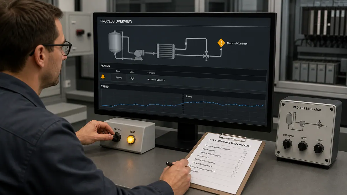
Alarm Banner and Summary
Alarm Banner Implementation: Create always-visible alarm notification:
Step 1: Design Alarm Banner
- Create banner area on all operator displays (typically 50-80 pixels height)
- Add alarm summary indicator showing:
- Current unacknowledged alarm count
- Highest priority active alarm
- Alarm state indication (flashing for unacknowledged)
- Configure click action opening alarm summary display
Step 2: Add Alarm Summary Object
- Insert "Alarm Summary" object in banner or dedicated display
- Configure display properties:
- Columns: Time, Priority, Message, State, Tag
- Sort Order: Priority descending, then time
- Filter: Show unacknowledged or all alarms
- Colors: Priority-based color coding
- Enable operator interaction:
- Click alarm to acknowledge
- Double-click for detail information
- Right-click for navigation to associated display
Step 3: Configure Alarm Acknowledgment Implement operator acknowledge workflow:
- Alarms appear in summary unacknowledged (flashing)
- Operator clicks to acknowledge alarm
- Acknowledged alarms remain visible until condition clears
- Alarm clears when process returns to normal
- Audit trail logs all acknowledge actions
Alarm Summary Display Configuration:
Full-Screen Alarm Summary: Create dedicated alarm management display:
- Full alarm history list (adjustable time window)
- Filter controls:
- Show all / unacknowledged only / shelved
- Priority range selection
- Equipment area filtering
- Time range selection
- Acknowledge controls:
- Acknowledge selected alarm
- Acknowledge all button
- Shelve alarm (temporary suppression)
- Navigation to equipment displays
- Alarm comment entry for documentation
Event Logging
Alarm and Event Logging Configuration:
Site Edition Alarm Logging:
Step 1: Configure Alarm Server
- Open FactoryTalk Alarms and Events setup
- Configure alarm log database:
- Database Type: SQL Server (recommended for production)
- Server Name: Database server instance
- Database Name: Alarm history database
- Authentication: Windows integrated or SQL authentication
- Set logging parameters:
- Log All Transitions: In-alarm, acknowledged, cleared
- Archive Interval: Move historical data to archive tables
- Retention Policy: Automatic purging of old records
Step 2: Configure Logged Information Capture comprehensive alarm data:
- Timestamp (alarm in, acknowledged, cleared)
- Tag name and current value
- Alarm message and priority
- Operator name (acknowledge actions)
- Comments entered by operators
- Equipment area and classification
Step 3: Access Historical Alarms Query alarm database for analysis:
- Alarm frequency by equipment
- Operator response times
- Most frequent alarms (rationalization targets)
- Alarm patterns and correlations
Machine Edition Event Logging: Limited logging capabilities in ME:
- Text file logging to local storage
- Circular buffer with size limits
- CSV export for external analysis
- No integrated database logging
Email Notifications
Automated Alarm Notification (Site Edition):
Step 1: Configure SMTP Settings
- Open FactoryTalk Alarms and Events setup
- Navigate to notification configuration
- Configure email server settings:
- SMTP Server: Mail server address
- Port: Typically 25 or 587
- Authentication: Username and password if required
- From Address: Alarm system sender address
Step 2: Create Notification Rules Define conditions triggering email notifications:
- Create new notification rule
- Set trigger conditions:
- Alarm priority threshold (e.g., priority < 100 = critical)
- Specific equipment areas or tags
- After-hours alarm notification
- Extended unacknowledged duration
- Configure recipients:
- Email addresses or distribution lists
- Different recipients based on conditions
- Escalation paths for unacknowledged alarms
Step 3: Configure Message Format Customize email notification content:
Subject: [ALARM] {Priority} - {Equipment} - {Message}
Body:
Alarm Details:
- Equipment: {Tag}
- Message: {Message}
- Priority: {Priority}
- Value: {CurrentValue}
- Time: {Timestamp}
- Status: {State}

This is an automated alarm notification from [Plant Name] SCADA System.
Notification Best Practices:
- Limit notifications to critical alarms only
- Avoid alarm flooding via rate limiting
- Test notification delivery regularly
- Maintain current distribution lists
- Include access instructions in notifications
Complete Alarm System Example
Comprehensive Tank Level Alarm Implementation:
Alarm Definitions:
Tank T-101 Level Alarms:
-
Level High-High (Priority 50 - Critical):
- Threshold: 95% level
- Message: "Tank T-101 - High-High Level 95% - Close Fill Valve Immediately"
- Acknowledge: Required
- Action: Automatic valve closure, operator verification
-
Level High (Priority 150 - Warning):
- Threshold: 85% level
- Message: "Tank T-101 - High Level 85% - Reduce Fill Rate"
- Acknowledge: Required
- Action: Operator reduces fill rate
-
Level Low (Priority 200 - Warning):
- Threshold: 15% level
- Message: "Tank T-101 - Low Level 15% - Start Fill Sequence"
- Acknowledge: Required
- Action: Operator initiates filling
-
Level Low-Low (Priority 75 - Critical):
- Threshold: 5% level
- Message: "Tank T-101 - Low-Low Level 5% - Risk of Pump Cavitation"
- Acknowledge: Required
- Action: Stop downstream pumps
Display Integration:
-
Tank graphic changes color on alarm state:
- High-High: Flashing red
- High: Solid yellow
- Normal: Green
- Low: Solid yellow
- Low-Low: Flashing red
-
Alarm banner shows most severe active alarm
-
Audible alert configured for critical priorities
-
Navigation button appears on tank graphic when alarmed, opening detail display with acknowledge capability
Alarm Logging: All alarm transitions logged to SQL database including:
- Operator acknowledge timestamps
- Comments entered explaining situation
- Corrective actions taken
- Alarm duration and frequency metrics
Email Notification: Critical alarms (High-High, Low-Low) trigger immediate email to:
- Operations supervisor
- Process engineer (after hours)
- Maintenance if equipment-related alarm
Result: Comprehensive alarm management providing operators with clear awareness of abnormal conditions, actionable information for response, and complete audit trail for regulatory compliance and continuous improvement.
Trends and Data Logging
Process visualization through trending enables operators to monitor performance, identify issues developing over time, and make informed control decisions. This section covers real-time and historical trending capabilities with comprehensive data logging configuration for analysis and compliance.
Real-Time Trends
Real-Time Trend Objects: Display current and recent process data for immediate visibility:
Step 1: Insert Trend Object
- Open display requiring trend visualization
- Select "Real-Time Trend" object from toolbox
- Place and size trend area appropriately (typically 400x300 minimum)
- Trend object provides live scrolling chart
Step 2: Configure Trend Properties Set overall trend characteristics:
- Right-click trend object → Properties
- Configure general settings:
- Time Span: Duration of visible history (1 min to 24 hours typical)
- Update Rate: Refresh interval (1-10 seconds typical)
- Grid: Enable gridlines for readability
- Legend: Show pen names and current values
- Scrollbar: Allow operator time navigation
Step 3: Add Trend Pens Configure data sources for trending:
- Open Pens tab in trend properties
- Add pen for each variable to trend
- Configure pen properties:
- Tag Name: Data source tag
- Color: Distinct color for identification
- Style: Solid, dashed, dotted line
- Width: Line thickness
- Min/Max Scale: Y-axis range for pen
- Visibility: Show/hide pen dynamically
- Label: Display name in legend
Example Configuration:
Pen 1: Tank T-101 Level
- Tag: Tank_T101.Level_PV
- Color: Blue
- Scale: 0-100%
- Style: Solid, Width 2

Pen 2: Tank T-101 Setpoint
- Tag: Tank_T101.Level_SP
- Color: Red
- Scale: 0-100%
- Style: Dashed, Width 1

Pen 3: Fill Valve Position
- Tag: Tank_T101.Fill_Valve_POS
- Color: Green
- Scale: 0-100%
- Style: Solid, Width 1
Step 4: Configure Trend Scaling Optimize display for data visibility:
- Fixed Scaling: Defined min/max for Y-axis (recommended for control variables)
- Auto-Scaling: Automatic adjustment to data range (useful for variables with wide ranges)
- Multiple Y-Axes: Different scales for pens with different engineering units
- Time Axis: Fixed or scrolling time window
Operator Interaction: Enable trend manipulation capabilities:
- Pan: Drag to view different time periods
- Zoom: Time zoom for detailed examination
- Cursors: Add cursors showing exact values at specific times
- Print: Print trend to document events
- Export: Save trend data to file
Historical Trends
Historical Trend Implementation (Site Edition):
Prerequisite: Data Logging Active Historical trends require logged data (configured in Data Logging section):
- Tags added to data log model
- Logging to SQL database configured
- Sufficient data retention policy
Step 1: Insert Historical Trend Object
- Select "Historical Trend" object from toolbox
- Place on display
- Size appropriately for data visualization
Step 2: Configure Historical Trend
- Open trend properties
- Configure data source:
- Database: SQL Server database name
- Table: Logged data table
- Time Range: Initial time span (1 hour to 30 days)
- Add pens referencing logged tags
- Configure display properties similar to real-time trends
Step 3: Time Navigation Controls Add operator controls for time selection:
- Start/end time input fields
- Predefined time range buttons:
- "Last Hour"
- "Last Shift (8 hours)"
- "Last Day"
- "Last Week"
- Date picker for specific date ranges
- Update button to refresh trend with selected timespan
Historical Analysis Capabilities:
- Compare current batch to historical batches
- Identify process drift over weeks/months
- Regulatory compliance documentation
- Post-event analysis for troubleshooting
- Optimization through performance comparison
Data Log Models
Configuring Continuous Data Logging (Site Edition):
Step 1: Create Data Log Model
- Right-click "Data Log Models" folder in Explorer
- Select "New Data Log Model"
- Name model descriptively: "Production_Line1_DataLog"
Step 2: Configure Logging Parameters Set overall model properties:
- Open data log model properties
- Configure settings:
- Database Type: SQL Server (recommended)
- Server: Database server name/IP
- Database: Database name
- Authentication: Windows or SQL authentication
- Table Prefix: Naming convention for log tables
- Logging Method:
- Periodic: Fixed interval (10 seconds to 1 hour typical)
- On-Change: Log when value changes beyond deadband
- Event-Triggered: Log on specific conditions
Step 3: Add Tags to Model Select tags for data logging:
- Click "Add Tags" button
- Browse tag database
- Select tags for logging:
- Process variables (temperature, pressure, flow, level)
- Setpoints and control outputs
- Production counts and rates
- Quality parameters
- Equipment status
- Configure per-tag properties:
- Deadband: Minimum change triggering log (reduces database size)
- Scaling: Engineering unit conversion if needed
- Description: Documentation for database queries
Step 4: Enable Data Logging
- Set data log model status to "Active"
- Verify logging begins in runtime
- Query database to confirm data storage:
SELECT TOP 100 *
FROM Production_Line1_DataLog
ORDER BY LogTime DESC
Database Table Structure: Typical logged data table schema:
- LogTime: Timestamp (primary key with tag)
- TagName: Tag identifier
- TagValue: Logged value
- Quality: Data quality indicator
- User: Operator if manually logged
Exporting Data to CSV/Database
Data Export Capabilities:
Manual Export from Trends:
- Display trend with desired data
- Right-click trend → Export Data
- Select format:
- CSV: Comma-separated values for Excel
- TXT: Tab-delimited text file
- XML: Structured data format
- Select time range and pens to export
- Save to file location
Automated Export Configuration: Schedule periodic data exports:
- Create VBA macro for export automation
- Configure scheduled task triggering macro
- Export to network share for analysis
Direct Database Access: Query SQL database for analysis:
-- Production Summary by Shift
SELECT
    CAST(LogTime AS DATE) as Date,
    DATEPART(HOUR, LogTime) as Shift,
    AVG(TagValue) as AvgProduction,
    MIN(TagValue) as MinProduction,
    MAX(TagValue) as MaxProduction
FROM Production_Line1_DataLog
WHERE TagName = 'Line1_Production_Rate'
    AND LogTime >= DATEADD(DAY, -7, GETDATE())
GROUP BY CAST(LogTime AS DATE), DATEPART(HOUR, LogTime)
ORDER BY Date, Shift
Third-Party Analytics Integration: Export data to analysis platforms:
- Excel pivot tables and Power BI dashboards
- Python/R statistical analysis
- MATLAB process modeling
- Tableau visualizations
- Custom web-based dashboards
Recipe Management
Recipe System Implementation:
Recipe Concept: Recipes store sets of setpoints and parameters for different products or operating modes, enabling rapid changeover without manual parameter entry.
Step 1: Define Recipe Structure Create recipe data organization:
- Define recipe parameters:
- Temperature setpoints
- Speed settings
- Timing parameters
- Quality specifications
- Organize parameters by equipment or process phase
Step 2: Create Recipe Files Configure recipe storage:
- CSV Files: Simple text-based recipes
- Database Tables: SQL Server recipe storage
- Structured Format: XML or JSON for complex recipes
Step 3: Recipe Display Interface Create operator interface for recipes:
- Recipe selector dropdown or list
- Load button transferring recipe values to PLC setpoints
- Current recipe indicator
- Recipe editor for authorized users
- Save current settings as new recipe
Step 4: Recipe Download Logic Implement VBA macro for recipe loading:
Private Sub LoadRecipe_Click()
    Dim recipeName As String
    Dim recipeFile As String
    Dim parameter As String
    Dim value As Single

    ' Get selected recipe
    recipeName = GetTag("Recipe_Selection")
    recipeFile = "C:\Recipes\" & recipeName & ".csv"

    ' Open recipe file and read parameters
    Open recipeFile For Input As #1
    Do While Not EOF(1)
        Input #1, parameter, value
        ' Write each parameter to PLC
        SetTag parameter, value
    Loop
    Close #1

    ' Confirm to operator
    MsgBox "Recipe " & recipeName & " loaded successfully"
End Sub
Result: Recipe management enables:
- Rapid product changeover (minutes vs hours)
- Consistent quality through repeatable settings
- Reduced operator error in parameter entry
- Recipe optimization without production disruption
- Complete recipe audit trail for validation
Complete Trending Example
Batch Temperature Control Trending:
Application: Monitor batch reactor temperature control during heating, reaction, and cooling phases.
Real-Time Trend Configuration: Create trend showing current batch progress:
- Pen 1: Reactor temperature PV (blue, 0-200°C)
- Pen 2: Temperature setpoint (red dashed, 0-200°C)
- Pen 3: Heating valve output (green, 0-100%)
- Pen 4: Cooling valve output (cyan, 0-100%)
- Time Span: 4 hours (typical batch duration)
- Update Rate: 5 seconds
- Alarm Limits: Dashed horizontal lines at high/low limits
Historical Trend Configuration: Compare batch performance:
- Same pen configuration as real-time
- Time range selector for specific batch dates
- Overlay multiple batches for comparison
- Print capability for batch records
- Integration with batch reporting system
Data Logging:
- Log all four parameters every 10 seconds
- Store to SQL database with batch identifier
- Retain 2 years for regulatory compliance
- Export capability to CSV for statistical analysis
Operator Display: Split screen showing:
- Left: Real-time trend for current batch
- Right: Historical trend showing last successful batch for comparison
- Batch phase indicator showing current step
- Time remaining estimate
- Deviation alarm if current batch differs significantly from expected profile
Result: Comprehensive trending system enabling:
- Operator awareness of process dynamics
- Early detection of control issues
- Batch-to-batch consistency verification
- Process optimization through historical comparison
- Regulatory compliance documentation
Runtime and Deployment
Transitioning from development to production operation requires comprehensive testing, proper deployment procedures, and thorough validation. This section covers runtime testing, application deployment to hardware, and troubleshooting common runtime issues.
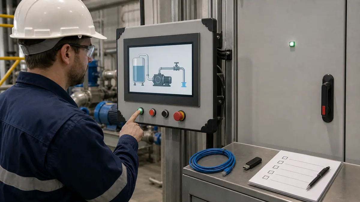
Testing in Runtime
Runtime Testing Environment:
Development Testing: Test applications during development using local runtime:
Step 1: Launch Test Runtime (Machine Edition)
- Save all changes in FactoryTalk View Studio
- Click "Run Application" button or select Runtime → Run from menu
- FactoryTalk View ME Station launches displaying startup screen
- Application runs on development PC for testing
Site Edition Testing:
- Start required servers (Data Server, Alarm Server)
- Launch FactoryTalk View SE Client
- Select test application
- Client connects to local servers for integrated testing
Step 2: Functional Testing Systematically validate all functionality:
Display Testing:
- All displays load without errors
- Graphics render correctly
- Animations operate smoothly
- Navigation buttons function properly
- Parameter passing works correctly
- Popups appear at intended positions
Communication Testing:
- Tag values update from PLC
- Write operations change PLC values
- Communication errors handled gracefully
- Scan rates adequate for application
- No communication timeouts under normal load
Alarm Testing:
- Alarms activate at correct thresholds
- Alarm messages display properly
- Acknowledgment functions correctly
- Alarm logging captures all transitions
- Email notifications send successfully
- Alarm prioritization displays correctly
Trend Testing:
- Real-time trends update properly
- Historical trends retrieve data correctly
- Trend scaling displays data clearly
- Cursor and zoom functions work
- Data export produces valid files
Security Testing:
- User login authentication works
- Permission levels restrict access appropriately
- Unauthorized actions prevented
- Audit trail logs security events
Step 3: Performance Testing Validate system performance under load:
- Multiple displays open simultaneously
- Response time for screen changes
- Update rate consistency under load
- Memory usage monitoring
- CPU utilization tracking
- Network bandwidth consumption
Step 4: Integration Testing Test complete system integration:
- PLC and HMI interaction
- Alarm system operation during process upsets
- Data logging captures all required information
- Recipe loading updates PLC correctly
- Reporting functions generate accurate data
Download to PanelView Plus
Deploying to Hardware Terminals:
Prerequisite: Hardware Preparation
- Install PanelView Plus terminal in panel
- Connect Ethernet cable to industrial network
- Power on terminal and verify boot
- Configure terminal Ethernet IP address
- Test communication to PLC
Step 1: Configure Application for Target Hardware In FactoryTalk View Studio:
- Verify display resolution matches PanelView screen size:
- PanelView Plus 7" Standard: 800 x 480
- PanelView Plus 7" Performance: 1280 x 800
- PanelView Plus 10": 1280 x 800
- PanelView Plus 12": 1280 x 800
- PanelView Plus 15": 1366 x 768
- Configure communication paths for PLC connectivity
- Set startup display and splash screen
- Configure runtime settings (screensaver, backlight, touchscreen calibration)
Step 2: Create Application Download
- Select Tools → Generate Runtime
- Studio compiles application into runtime format
- Verify no compilation errors
- Creates .MER runtime file
Step 3: Download to PanelView Using FactoryTalk View ME Station:
- Connect development PC to same network as PanelView
- Launch FactoryTalk View Studio Administration Console
- Select "Load Application" option
- Browse to PanelView IP address
- Select application runtime file (.MER)
- Transfer application to PanelView (several minutes depending on size)
- Configure startup options
- Reboot PanelView to load new application
Alternative: SD Card Deployment For terminals without network connectivity:
- Generate runtime application
- Copy .MER file to SD card
- Insert SD card into PanelView
- Use terminal configuration menu to load from SD card
- Application installs to internal storage
Deploy to a PanelView Plus: The .mer File and Transfer Utility
Understanding the ME deployment mechanism in detail saves significant commissioning time. Here is what actually happens and why each step matters.
What is a .mer file? The .mer file is the compiled Machine Edition runtime application. When you click "Generate Runtime" in FactoryTalk View Studio, the development environment compiles all your displays, tags, macros, alarm definitions, and communication paths into a single binary package. The PanelView Plus loads and runs this .mer file directly — it does not need Studio installed. Think of it like an executable; the Studio project (.med) is the source, and the .mer is the compiled output.
What is the FactoryTalk View ME Transfer Utility? The Transfer Utility is a standalone tool (installed with Studio) that sends the .mer file to a PanelView Plus terminal over the network. It uses FactoryTalk Linx/RSLinx Enterprise for the network path to the terminal, not a direct file copy. You must have communication to the terminal configured in Linx before the Transfer Utility will find it.
Step-by-step: compile and transfer procedure
- In FactoryTalk View Studio (ME), resolve all compilation errors — check the error/warning pane.
- Select Tools → Generate Runtime Application. Studio compiles the project and saves a
.merfile to the specified output folder. - Confirm the target PanelView Plus is powered on, connected to the network, and has an IP address on the same subnet as the development PC.
- Verify the terminal is reachable: open FactoryTalk Linx and confirm the PanelView appears as a discovered device.
- Launch FactoryTalk View ME Transfer Utility (Start menu → Rockwell Software).
- In Transfer Utility, select Download and browse to the compiled
.merfile. - Select the destination terminal from the device browser (populated via FactoryTalk Linx).
- Click Download. Transfer time depends on application size — a few minutes is typical for a medium-sized project.
- The terminal will restart and load the new application automatically after a successful transfer.
Critical: firmware version matching. The firmware on the PanelView Plus terminal must be compatible with the version of FactoryTalk View ME used to compile the .mer file. If versions are mismatched, the terminal will reject the file or display a firmware mismatch error. Always check the PanelView Plus firmware version (visible in the terminal's configuration menu) against Rockwell's compatibility matrix in the PCDC before generating a runtime. Firmware updates are applied via the same Transfer Utility or via SD card using a firmware .dmk file.
Creating Application Packages
Application Backup and Portability:
Use the FactoryTalk View Application Manager supplied with the installed release for supported backup and restore workflows. A local ME or supported local SE application archive commonly uses the .apa extension; a compiled ME runtime uses .mer. They are different artifacts.
Before trusting an archive:
- Confirm the source application name, View edition/version/patch, Windows build, target terminal/firmware, and activation.
- Create the archive with the release-specific Application Manager procedure.
- Inventory dependencies outside the archive: FactoryTalk Directory/security, data servers, certificates, ActiveX/.NET controls, fonts, scripts, SQL or InfluxDB stores, historian configuration, service accounts, and companion products.
- Restore to an isolated compatible environment under a new test name.
- Verify displays, communications, alarms, history, security, scripts, recipes, reports, and deployment generation against the acceptance worksheet.
A successful archive creation message proves that a file was written; only a restore and functional test proves recoverability. Distributed SE systems require the architecture-specific Rockwell backup procedure and infrastructure backup, not merely a local application archive.
Backup and Restore
Comprehensive Backup Strategy:
Development Backups: Regular source backups during development:
- Create scheduled backup task
- Backup entire application folder structure:
- .MED or .SED application files
- Graphics folder
- Tag databases
- Custom graphics libraries
- Documentation
- Store to network location and offline media
- Maintain versioned backups (daily, weekly, monthly)
- Test restore procedures periodically
Runtime Backups: Backup deployed applications:
PanelView Plus Backup:
- Connect to PanelView via Administration Console
- Select "Upload Application" option
- Save runtime application from terminal to PC
- Store backup with version information
- Backup frequency: After any changes, before firmware updates
Site Edition Server Backup:
- Backup SQL Server databases (alarms, data logs)
- Backup server application files
- Backup FactoryTalk Security databases
- Document server configuration
- Create complete system image backup
Restore Procedures: Document restore processes:
- Verified backup media available
- Step-by-step restore instructions
- Communication reconfiguration requirements
- Testing checklist after restore
- Emergency contact information
Remote Access Setup
Configuring Remote Access (Site Edition):
VantagePoint Web Clients: Browser-based HMI access:
Step 1: Configure Web Server
- Install FactoryTalk ViewPoint server component
- Configure IIS web server
- Set up HTTPS with SSL certificate for security
- Configure authentication methods
- Test local web browser access
Step 2: Client Access Remote users access via web browser:
- Navigate to server URL: https://servername/ViewPoint
- Login with FactoryTalk Security credentials
- Select application to view
- HMI displays in browser window
- Interact with displays (viewing and control)
VPN Remote Access: Secure remote desktop access:
- Configure VPN server on plant network
- Remote users connect via VPN client
- Access HMI via remote desktop to operator stations
- Full functionality available through VPN tunnel
- Implement security policies for remote access
Mobile Access: Smartphone and tablet access:
- Use VantagePoint with responsive displays
- Configure mobile-optimized screen layouts
- Test on target mobile platforms
- Implement appropriate security restrictions
- Limit control capabilities from mobile devices
Troubleshooting Runtime Issues
Common Issues and Resolutions:
Issue 1: Application Fails to Start Symptoms: Runtime exits immediately or shows error message
Troubleshooting:
- Check FactoryTalk Activation status (license valid?)
- Verify all required services running (FactoryTalk Linx)
- Review error logs in Event Viewer
- Test application in development environment
- Regenerate runtime and redeploy
Issue 2: No PLC Communication Symptoms: Tags show "???" or incorrect values
Troubleshooting:
- Verify PLC network connectivity (ping PLC IP address)
- Check RSLinx communication paths
- Confirm PLC in Run mode and accessible
- Verify tag addresses in HMI match PLC program
- Check firewall settings on PC
- Test communication with RSLinx Diagnostic tools
- Review communication settings in tag database
Issue 3: Slow Display Updates Symptoms: Delayed response, sluggish animations
Troubleshooting:
- Check network communication scan times
- Reduce number of tags on single display
- Optimize communication update rates
- Close unused displays consuming resources
- Increase PC/PanelView processing capacity
- Simplify complex graphics and animations
- Monitor CPU and memory utilization
Issue 4: Alarms Not Logging Symptoms: Alarm database not receiving entries
Troubleshooting:
- Verify SQL Server connectivity
- Check database permissions for HMI user
- Confirm alarm server running (Site Edition)
- Review alarm configuration enabled for logging
- Check disk space on database server
- Test database connection manually
Issue 5: Displays Appear Incorrectly Symptoms: Graphics misaligned, objects missing
Troubleshooting:
- Verify display resolution matches target hardware
- Confirm all fonts installed on runtime system
- Check custom graphics libraries present
- Regenerate runtime application
- Verify graphics files not corrupted
- Test on different hardware to isolate issue
Diagnostic Tools: Utilize built-in diagnostics:
- FactoryTalk Diagnostics Viewer: System logs and errors
- RSLinx Diagnostics: Communication status
- Windows Event Viewer: Application and system errors
- Task Manager: Performance monitoring
- Network Monitoring Tools: Communication bandwidth
Technical Support Resources: When issues persist:
- Rockwell Automation Technical Support
- Rockwell Knowledgebase (TechConnect)
- Online communities (PLCTalk, Reddit r/PLC)
- Certified System Integrators
- Local distributor technical support
Troubleshooting: Symptom → Cause → Fix
The table below covers useful failure modes to test during development and commissioning, including several that only appear when deploying to physical PanelView Plus hardware.
| Symptom | Most likely cause | Fix |
|---|---|---|
| Tags show "???" in runtime | No RSLinx/FactoryTalk Linx shortcut created, or shortcut name in tag address is wrong | Open FactoryTalk Linx, verify shortcut exists and name matches tag addresses exactly. Re-browse tags. |
| Tag browser empty in Studio | FactoryTalk Linx Gateway service not running | Open Services (services.msc), confirm "FactoryTalk Linx Gateway" is running. Restart if stopped. |
| Transfer Utility cannot find PanelView | Terminal not visible in FactoryTalk Linx, or on a different network segment | Confirm PanelView IP address; verify PC and terminal are on the same subnet; check Linx device browser. |
| Terminal rejects .mer file with firmware error | PanelView Plus firmware version incompatible with Studio version used to compile | Check terminal firmware version in its configuration menu; update firmware via SD card .dmk file or match Studio version to firmware. Use PCDC compatibility matrix. |
| Display renders incorrectly / objects misaligned on terminal | .mer compiled at wrong resolution for the physical screen | In Studio, verify project display resolution matches the exact PanelView Plus model (e.g., 800x480 for 7" Standard, 1280x800 for 7" Performance). Regenerate and redeploy. |
| Offline activation fails | Windows date/time incorrect, or administrator privileges not used | Set correct system date/time; run FactoryTalk Activation Manager as administrator. |
| Alarms trigger but do not log | SQL Server service stopped, database permissions wrong, or disk full | Verify SQL Server is running; check HMI service account has db_datawriter permission; check disk space. |
| Application compiles with no errors but crashes on startup | Missing font or graphic file not embedded in .mer | Ensure all custom fonts are installed on the development PC before compiling; re-run Generate Runtime. |
| Tags update slowly or lag > 1 second | Too many tags on one display, or communication scan rate set too high | Review tag update rates; disable updates on hidden/inactive displays; check network latency to PLC. |
Best Practices
Implementing established best practices ensures professional-quality applications that are maintainable, scalable, and operator-friendly. This section consolidates industry-proven techniques for FactoryTalk View development.
Screen Design Principles
Visual Hierarchy and Layout:
Consistent Layout Structure: Establish standard screen organization:
- Header Area (80-100 pixels): Navigation, title, user info, time
- Main Content Area: Process graphics and controls
- Footer/Status Area (60-80 pixels): Alarm summary, system status
- Navigation Column (optional): Left or right sidebar with menu
Color Standards: Implement consistent, meaningful color scheme:
Equipment Status Colors (ISA 101 Standard):
- Gray: Equipment off/disabled
- Green: Equipment running normally
- Yellow: Equipment in transition or warning state
- Red: Equipment faulted or emergency stopped
- Blue: Equipment under external control
Alarm Colors:
- Red: High priority, critical alarms
- Orange: Medium priority, urgent warnings
- Yellow: Low priority, advisory alarms
Background Colors:
- Dark Gray (RGB: 64,64,64): Reduces eye fatigue
- Light Gray (RGB: 192,192,192): Alternative for high ambient light
- Avoid pure white backgrounds (harsh on eyes)
Typography Standards: Readable text enhances usability:
- Display Titles: Arial Bold, 24-32pt
- Equipment Labels: Arial, 14-18pt
- Numeric Values: Arial Bold, 16-24pt depending on importance
- Button Text: Arial Bold, 16-20pt for touch targets
- Minimum Text Size: 12pt for readability
Touchscreen Considerations: Design for finger-operated controls:
- Minimum Button Size: 40x40 pixels (fingertip target)
- Button Spacing: 10-pixel minimum separation
- Touch Feedback: Visual indication on press (color change, border)
- Avoid Small Targets: No click targets smaller than 30x30 pixels
Performance Optimization
Display Optimization:
Limit Objects Per Display:
- Maximum Objects: 200-300 objects per display maximum
- Active Animations: Limit to 50-75 simultaneously animated objects
- Embedded Displays: Use sparingly (2-3 maximum per screen)
- Complex Graphics: Simplify or use pre-rendered images
Communication Optimization:
Tag Update Rates: Configure appropriate scan rates:
- Critical Control Values: 100-250ms update rate
- Standard Process Variables: 500ms-1s update rate
- Slow-Changing Values: 2-5s update rate
- Status Information: 5-10s update rate
- Minimize Unnecessary Polling: Disable updates for invisible objects
Communication Grouping: Organize tags efficiently:
- Group related tags in PLC for efficient communication packets
- Use arrays in PLC for sequential data
- Implement tag-based communication shortcuts
- Monitor communication bandwidth and optimize
Database Performance:
Alarm and Data Logging:
- Index database tables on timestamp columns
- Implement automatic archiving of old data
- Regular database maintenance (rebuild indexes, update statistics)
- Monitor database size and growth
- Set appropriate retention policies
Alarm Management Strategies
ISA 18.2 Alarm Management:
Alarm Rationalization: Every alarm must justify existence:
- Consequence: What happens if alarm ignored?
- Operator Response: What specific action should operator take?
- Priority Assignment: Appropriate urgency level
- Threshold Setting: Eliminates nuisance alarms
Alarm performance review:
- Standing/stale alarms: Track age, priority, source, owner, and resolution
- Alarm rate and floods: Calculate by console and operating state over the adopted window
- Bad actors and chattering: Rank sources and retain before/after evidence
- Non-actionable notifications: Evaluate as events or status instead of alarms
Alarm Prioritization: Enforce strict priority discipline:
- Critical (High): Immediate response prevents safety/environmental/major economic consequence
- Urgent (Medium): Prompt response prevents process upset or equipment damage
- Warning (Low): Awareness of abnormal condition, scheduled response acceptable
Nuisance Alarm Prevention: Techniques to reduce unnecessary alarms:
- Deadbands: Prevent alarms near threshold from chattering
- Time Delays: Alarm activates only after condition persists
- State-Based Alarming: Disable alarms during relevant equipment states (startup, shutdown)
- Shelving: Temporary alarm suppression with audit trail
Reusable Templates
Template Development:
Global Object Templates: Create reusable components:
- Navigation headers
- Alarm banners
- User login displays
- Equipment faceplates
- Standard popup dialogs
Parameterized Displays: Equipment-agnostic displays:
- Motor control faceplates accepting motor number
- Tank displays with tank identifier parameter
- Valve control dialogs with valve parameter
- Pump faceplates for identical pumps
Standard Graphics Library: Maintain company-specific library:
- Custom equipment symbols
- Corporate branding elements
- Standard button styles
- Color palettes and themes
- Import library to all new projects
Add-On Instruction Integration: Align HMI displays with PLC Add-On Instructions:
- Match faceplate to AOI parameters
- Consistent naming between PLC and HMI
- Documentation referencing both PLC and HMI
Version Control
Application Versioning:
Version Numbering: Implement semantic versioning:
- Format: Major.Minor.Patch (e.g., 2.1.5)
- Major: Significant functionality changes
- Minor: New features, non-breaking changes
- Patch: Bug fixes and minor improvements
Change Documentation: Maintain comprehensive change log:
Version 2.1.5 (2025-12-11)
- Fixed alarm acknowledgment issue on Tank T-101
- Added production count trend to Line 1 Overview
- Updated motor faceplate template with new status indicators
- Corrected communication path for Line 2 PLC
Backup Before Changes: Standard procedure before modifications:
- Create dated backup of current application
- Document baseline version number
- Make and test changes
- Increment version number
- Update change log
- Create new backup of modified version
Project Documentation:
Documentation Standards: Maintain comprehensive project documentation:
Application Documentation:
- System architecture diagram (network, servers, clients)
- Tag database documentation with descriptions
- Alarm list with priorities and response procedures
- Display navigation map showing screen hierarchy
- Communication configuration documentation
- Security policy and user role definitions
Operator Documentation:
- User manual with screenshots of all displays
- Normal operation procedures
- Alarm response procedures
- Startup and shutdown procedures
- Common troubleshooting guide
Maintenance Documentation:
- Software version information
- Backup and restore procedures
- System administration guide
- Troubleshooting and diagnostics
- Upgrade and migration procedures
- Vendor contact information
Training Materials:
- Operator training presentations
- Hands-on training exercises
- Video tutorials for complex procedures
- Quick reference cards for common tasks
FactoryTalk View vs FactoryTalk Optix — Which to Learn in 2026?
This is a question that almost nobody covers, yet it is increasingly relevant for engineers choosing where to invest their learning time.
What is FactoryTalk Optix?
FactoryTalk Optix is Rockwell Automation's newer visualization platform built on an HTML5/web-native architecture with OPC UA as its native communication protocol. It is designed for cross-platform deployment — running on industrial PCs, browsers, and Rockwell's OptixPanel hardware — and is positioned for greenfield applications that require cloud connectivity, web-based HMI access, or modern development workflows.
Key Optix characteristics:
- HTML5/web-native rendering (no proprietary runtime plugin)
- OPC UA native (works with non-Rockwell PLCs out of the box)
- Runs on OptixPanel terminals, Windows IPCs, and browsers
- Modern IDE with object-oriented project structure
- Well-suited for IIoT, cloud historian integration, and edge computing
Is FactoryTalk View ME/SE end-of-life?
No. As of 2026, FactoryTalk View ME and SE are actively maintained, sold, and deployed. Rockwell has not announced end-of-life for either edition. The installed base of PanelView Plus terminals and existing FTV SE SCADA systems is enormous, and support timelines extend well into the future. Optix coexists with and adds to the portfolio — it does not replace FTV.
The "PanelView 5000" clarification
A common misconception worth correcting: PanelView 5000 terminals do not run FactoryTalk Optix. PanelView 5000 uses Studio 5000 View Designer — a separate, dedicated development tool that is part of the Studio 5000 suite. FactoryTalk Optix runs on OptixPanel hardware and on IPCs/browsers. These are three distinct hardware families with three distinct development tools.
| Hardware family | Development tool |
|---|---|
| PanelView Plus 7 / Plus 6 | FactoryTalk View Studio (Machine Edition) |
| PanelView 5000 | Studio 5000 View Designer |
| OptixPanel / IPCs / browsers | FactoryTalk Optix |
Which should you learn?
Learn FactoryTalk View ME/SE if:
- You will work on existing Allen-Bradley installations (the majority of North American manufacturing)
- Your projects involve PanelView Plus terminals
- Local employers and installed systems explicitly require FactoryTalk View skills
- Your plant has an existing FTV SE SCADA that needs expanding or maintaining
Consider FactoryTalk Optix if:
- You are designing a greenfield system with no requirement for PanelView Plus hardware
- The project requires web-based HMI, cloud historian, or browser access without a VPN
- You need native OPC UA connectivity to multi-vendor equipment
- The customer or integrator explicitly specifies Optix
Practical verdict for 2026: Learn the platform installed at the plant or required by the project. For an existing PanelView Plus or View SE system, FactoryTalk View is the relevant maintenance skill. Evaluate Optix separately for a greenfield project using its current hardware, browser, protocol, lifecycle, and licensing requirements.
Frequently Asked Questions
What is FactoryTalk View used for?
FactoryTalk View is Rockwell Automation's human-machine interface (HMI) and SCADA software platform used to create graphical operator interfaces for Allen-Bradley PLC control systems. The software enables visualization of industrial processes, operator control of equipment, alarm management, data logging, and trending for manufacturing and process automation applications. FactoryTalk View scales from standalone machine interfaces on PanelView Plus terminals (Machine Edition) to distributed plant-wide SCADA systems with multiple operator stations (Site Edition).
What is the difference between FactoryTalk View ME and SE?
Machine Edition (ME) is a standalone HMI architecture where the application runs on a machine-level terminal or PC runtime. Site Edition (SE) uses a distributed client-server architecture for applications that need central services and multiple operator stations. Select between them from the required architecture, target hardware, alarms, history, redundancy, users, integrations, and a dated same-scope licence quote.
How do I connect FactoryTalk View to my PLC?
Use the communication software and workflow supported by the installed View release. Confirm IP routing and the controller in FactoryTalk Linx, create the application communication shortcut, map that shortcut to the development and runtime controller paths, then browse or bind one known test tag. Run an offline test where possible and a controlled runtime test on an isolated system. Do not copy an address string from another project: shortcut names, controller paths, program scope, and tag external-access settings are project-specific.
Can I import tags from Studio 5000?
FactoryTalk View can reference Logix controller tags through a configured shortcut, and release-specific tools can support tag browsing or import workflows. Use the Rockwell help for the exact View and Logix releases, because controller tags, HMI tags, program-scoped tags, and exported CSV files are different mechanisms. Test one Boolean, one numeric, one array or structure member, and write permissions before scaling the mapping.
How do I create animations in FactoryTalk View?
Create animations by selecting objects on displays and configuring animation properties through right-click menus. Common animation types include Color (change object colors based on tag values), Visibility (show/hide objects conditionally), Position (move objects horizontally or vertically for sliders and level indicators), Rotation (rotate objects for motors and rotating equipment), and Size (scale objects for bar graphs and tank levels). Configure each animation by selecting the animation type, entering the tag expression determining behavior, and defining the value ranges and corresponding visual states. Multiple animations can be applied to single objects for complex behaviors like a tank that changes both level height and color based on process values.
What is the cost of FactoryTalk View?
Rockwell does not provide one durable public price that covers every FactoryTalk View deployment. Cost depends on ME or SE edition, development and runtime activations, capacity, clients, servers, communication components, redundancy, history, support, term, region, and hardware. Build a complete licence worksheet and request a dated Rockwell or authorised-distributor quote.
Can FactoryTalk View work with non-Allen-Bradley PLCs?
Non-Rockwell connectivity depends on the View edition, release, supported data server or gateway, protocol, and the third-party device. Verify the complete route in Rockwell and gateway compatibility documentation, including data types, write behavior, quality, redundancy, security, and support ownership. Do not assume that an OPC label makes every PLC integration equivalent.
How do I troubleshoot communication issues?
Troubleshoot the configured path layer by layer: confirm the approved network route, controller and communication-server diagnostics, application shortcut, development path, runtime path, controller or program tag scope, data quality, and write permission. Compare the working and failing nodes before changing firewalls or controller settings. Use Rockwell's release-specific port and compatibility documentation; a single hard-coded port is not a complete FactoryTalk architecture.
What HMI hardware works with FactoryTalk View?
Machine Edition targets supported PanelView Plus terminals and supported PC-based ME Station configurations; Site Edition clients and servers use supported Windows environments. Exact terminal models, display sizes, operating systems, firmware, computer resources, and activations change by release. Confirm them in PCDC and the current installation guide for the selected version rather than using a generic hardware minimum.
How do I backup my FactoryTalk View project?
Back up the editable application separately from a deployable runtime. For ME, use the release-specific Application Manager workflow to create and verify an application archive (commonly an .apa), and retain the tested .mer, terminal/firmware record, communications, fonts, ActiveX dependencies, and activation information needed for recovery. Do not assume a runtime can always be converted back into complete editable source.
For SE, use Rockwell's supported backup/restore procedure for the selected local or network-distributed architecture and include the application, FactoryTalk Directory and security dependencies, data/alarm/history stores, certificates, service accounts, companion products, and infrastructure configuration in scope. Derive frequency and retention from RPO and change rate. Restore the backup into an isolated environment and run the acceptance test; a copied file that has never been restored is not recovery evidence.
Can I use VBA scripting in FactoryTalk View?
FactoryTalk View SE supports client-side VBA in supported contexts; FactoryTalk View ME does not provide the same SE VBA model. Confirm the object, event, client/server execution location, security context, 32/64-bit dependency, and release support before designing around a script. Keep deterministic machine control and safety behavior in the validated controller/safety system, not in an HMI script. Rockwell also documents .NET controls and other extensibility for particular SE releases; that is not a blanket “.NET scripting” capability across both editions.
What is FactoryTalk Linx?
FactoryTalk Linx provides communications and device-browsing services used by FactoryTalk applications. FactoryTalk Linx, FactoryTalk Linx Gateway, and RSLinx Classic are distinct products and entitlements; do not assume one universally replaces the others or that every driver, OPC interface, redundancy option, or gateway function is included. Select the required edition and version from the application's protocol, client interface, topology, security, redundancy, and support requirements, then validate the route with one read, one authorized write, quality loss, reconnection, and failover where applicable.
Conclusion
FactoryTalk View Studio represents a comprehensive, capable HMI development platform deeply integrated within the Rockwell Automation ecosystem. Mastering FactoryTalk View empowers automation professionals to create professional operator interfaces ranging from simple machine panels to sophisticated plant-wide SCADA systems supporting operational excellence initiatives.
Key Takeaways:
Platform Selection: Choose Machine Edition for standalone machine interfaces on PanelView Plus terminals where single operator stations suffice and budget constraints prioritize cost-effective solutions. Select Site Edition for plant-wide systems requiring multiple operator stations, centralized alarm management, comprehensive data logging to SQL databases, and enterprise integration capabilities. The edition selection fundamentally impacts system architecture, costs, and scalability.
Development Foundation: Successful FactoryTalk View development requires solid foundation in graphic design principles, tag database organization, communication configuration, and operator-centric interface design. Invest time learning best practices for screen layout, color usage, animation techniques, and navigation structure before tackling complex applications. These fundamentals apply universally across HMI platforms and represent transferable skills.
Integration Excellence: FactoryTalk View excels when fully integrated with Studio 5000 Logix Designer, FactoryTalk Linx communication, and the broader FactoryTalk suite. Leverage tag import from Studio 5000 for consistency, implement comprehensive alarming aligned with ISA 18.2 standards, and utilize data logging for production analytics and continuous improvement. The platform's strength emerges through ecosystem integration rather than standalone usage.
Career Development: FactoryTalk View is relevant when a role supports a Rockwell automation estate. Combined with Studio 5000 skills, it lets an engineer work across controller logic and operator interfaces; the employment value depends on the installed systems and requirements in the target market.
Next Steps:
Hands-On Practice: Theory alone cannot develop practical proficiency. Contact your local Rockwell Automation distributor about evaluation licensing options, work through tutorial exercises, experiment with different graphic techniques, and build sample applications emulating real industrial processes. Use emulation software or virtual PLCs for offline development without requiring physical hardware investment.
Complementary Learning: Expand your Rockwell automation expertise by exploring related topics:
- RSLogix 500 vs RSLogix 5000 comparison for understanding PLC platform evolution
- TIA Portal vs Studio 5000 comparison for multi-vendor platform perspective
- Siemens vs Allen-Bradley comparison for comprehensive automation platform selection guidance
Real-World Application: Apply learned concepts to actual industrial projects gaining experience with production systems, operator feedback, and long-term maintenance requirements. Real-world experience reveals practical considerations rarely addressed in tutorials, developing judgment essential for professional-quality applications.
FactoryTalk View can support effective operator interfaces when the exact edition and release fit the architecture and the application is designed, tested, documented, and maintained around operator tasks.
Begin in an isolated lab or vendor-supported evaluation environment, work through the acceptance worksheet, and progress to hardware only under the site's electrical-safety and change-control procedures.


