PLC Temperature Control: Sensors, Logic, PID and Tests
Build a PLC temperature-control loop from sensor and quality checks through on/off, staged or PID control, actuator proof, commissioning and fault diagnosis.
Direct answer
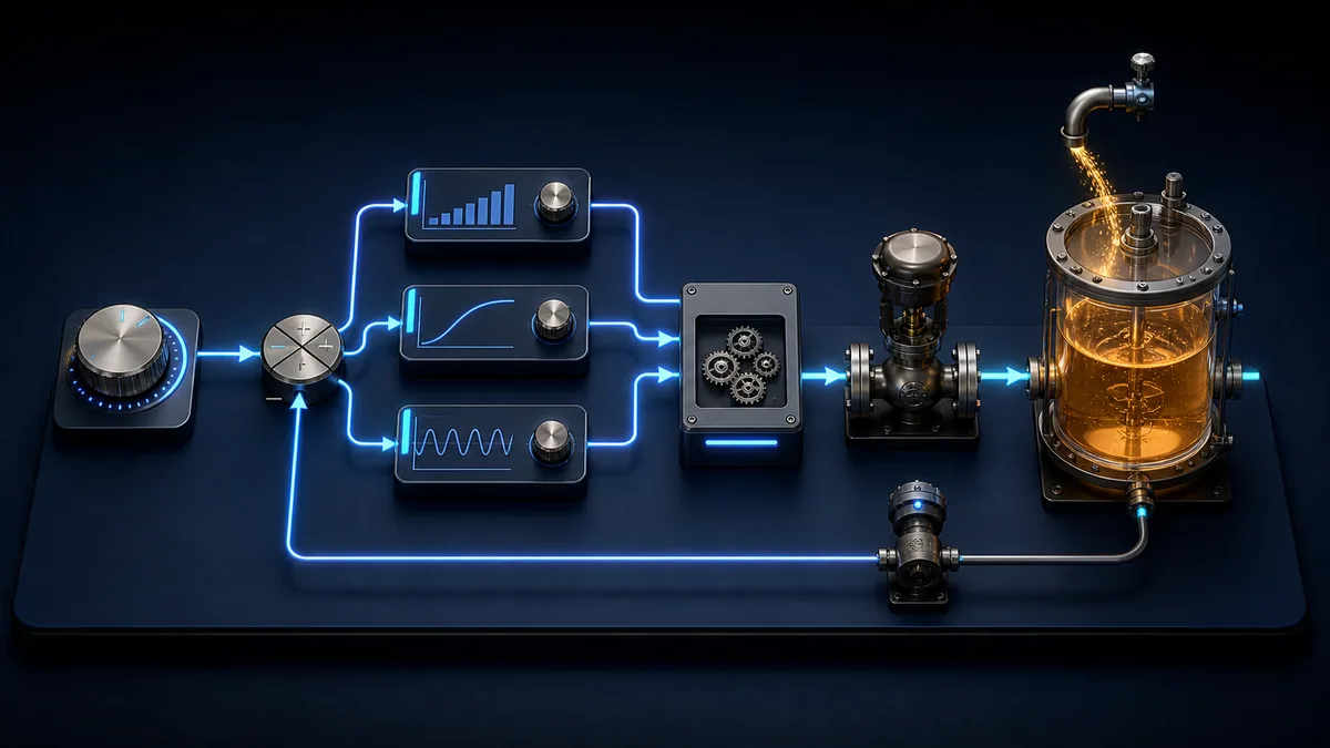
PLC temperature control is a closed or bounded control function in which a PLC reads a temperature sensor, validates signal quality, converts the measurement into engineering units, compares it with a setpoint and commands a heater, valve, fan or cooling device. A complete program does more than calculate an output: it establishes sensor and actuator contracts, selects on/off, staged, time-proportioned or PID control to match the process, manages modes, proves commanded equipment, detects bad or stale measurements, enforces independent operating limits and records evidence for commissioning and diagnosis.
For a simple heater, on/off control with hysteresis can be enough: turn heat on below SP − 2 °C and off above SP + 2 °C. A slow thermal process that needs tighter regulation may justify a PID loop executed at a known interval. Neither strategy replaces a separate overtemperature limit, safety function, correctly sized final element or approved process-hazard analysis.
Download the temperature-loop signal contract, control-strategy selection worksheet and commissioning acceptance matrix. They preserve the assumptions, boundaries and evidence discussed below.
What this guide owns
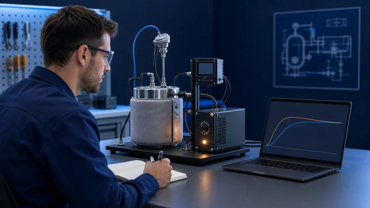
This page owns the implementation path for a general PLC temperature-control application: requirements, sensor input, scaling, quality, control-strategy choice, executable vendor-neutral logic, final-element proof, commissioning and troubleshooting. The worked example is an electrically heated chamber, but the contracts also apply to a jacket valve, chilled-water valve or fan after correcting the action direction and failure behavior.
The PID control-system example explains PID arithmetic. The PLC PID program guide goes deeper into controller forms, timing and mode tracking. The PID tuning guide owns tuning methods. Use the analog input scaling guide for measurement calculations and the Delta temperature-module guide for one vendor-specific device example. Keeping these jobs separate prevents a general example from pretending to be a vendor configuration, universal sensor-selection guide or tuning prescription.
| Reader task | Best owner | Boundary |
|---|---|---|
| Build a complete temperature-control program | this guide | sensor-to-actuator implementation and tests |
| Understand one PID calculation | PID control-system example | arithmetic and response interpretation |
| Wrap a PLC PID instruction correctly | PID program guide | task timing, modes, tracking and limits |
| Select and tune gains | PID tuning guide | known process and performance objective |
| Configure a specific temperature module | vendor specialist | exact model, channel, buffer and diagnostics |
| Design a safety instrumented function | qualified safety lifecycle | independent hazard analysis and validated protection |
Start with the control contract
Define controlled and manipulated variables
Write the objective in measurable terms before opening the PLC editor. For the teaching chamber, the controlled variable is internal air temperature in degrees Celsius. The manipulated variable is applied heater power from 0 to 100%. Ambient temperature and door opening are disturbances. The heater contactor or solid-state power controller is the final control element. A separate high-temperature device removes heat authorization independently of ordinary control logic.
“Hold temperature accurately” is not testable. A better requirement states the permitted operating range, target, normal load envelope, maximum approach rate or overshoot, settling criterion, sensor fault response, output limits, proof timeout, manual-mode authority, restart state, alarm delay and evidence retention. It distinguishes product-quality limits from equipment-protection and personnel-safety limits.
| Contract item | Teaching value | Project evidence |
|---|---|---|
| normal setpoint range | 40–80 °C | approved recipe or operator bound |
| measurement range | 0–300 °C | sensor, transmitter and module records |
| normal output | 0–100% request | heater or valve authority calculation |
| control interval | 1.0 s | periodic-task configuration and trace |
| bad-input response | heat request forced to 0% | simulated/open-circuit test |
| independent high limit | project-specific | separate device/function proof record |
| restart behavior | manual, output 0% | power-cycle acceptance test |
| feedback proof | auxiliary/current feedback in 2 s | command-feedback trend |
Separate request, permission, command and feedback
One Boolean called Heater hides too much. Preserve at least HeatRequest, HeatPermissive, HeatCommand and HeatFeedback. The controller owns the request. Equipment and protection conditions determine permission. Output arbitration creates the command. An auxiliary contact, current relay, valve position or another suitable measurement provides feedback. A timeout between command and feedback identifies a failed boundary instead of blaming PID.
The same separation applies to analog demand: keep raw PID output, bounded request and applied or feedback-confirmed output as different values. If a high selector, output limit, equipment interlock or downstream controller changes demand, the PID's tracking or anti-windup facility needs the value the process can actually receive.
Temperature sensor and input design
Choose the sensor for the process
RTDs, thermocouples and transmitters solve different measurement problems. IEC 60751 defines industrial platinum-resistance thermometer characteristics. IEC 60584-1 covers thermocouple EMF specifications and tolerances, while NIST publishes ITS-90 reference tables. Those standards do not choose a sensor; the range, accuracy, response, sheath, insertion, vibration, chemistry, wiring distance, isolation, maintenance and hazardous-area requirements do.
| Input route | Strength | Typical failure evidence | Programming concern |
|---|---|---|---|
| direct RTD module | stable precision over moderate ranges | open/short, lead imbalance, status | sensor type and 2/3/4-wire support |
| direct thermocouple module | wide range and small junction | open, polarity, extension alloy, CJC status | type, units and compensation behavior |
| 4–20 mA transmitter | long cable, isolation, local diagnostics | under/overrange, loop loss, status | raw limits and live-zero interpretation |
| digital smart transmitter | value plus diagnostics | stale update, bad status, link loss | quality, age, profile and fallback |
Do not “repair” wrong polarity, sensor type or lead compensation with a convenient software multiplier or offset. Prove the sensor at known points and inspect each boundary. Scaling converts representation; calibration compares the measurement chain with a traceable reference. They are related but not interchangeable.
Scale raw input with declared endpoints
Suppose an input represents 4–20 mA as raw counts 5,530 to 27,648, and the transmitter range is 0–300 °C:
Temperature_C = (Raw − 5530) × (300 − 0) / (27648 − 5530) + 0
At raw 14,980, the result is about 128.2 °C. Preserve the raw value, scaled value, configured endpoints and units. Clamp only where appropriate; do not clamp away raw underrange and overrange evidence needed for fault detection.
| Calculation item | Value |
|---|---|
| raw span | 27,648 − 5,530 = 22,118 counts |
| raw above lower endpoint | 14,980 − 5,530 = 9,450 counts |
| normalized fraction | 9,450 / 22,118 = 0.42725 |
| scaled temperature | 0.42725 × 300 = 128.2 °C |
Give quality its own state
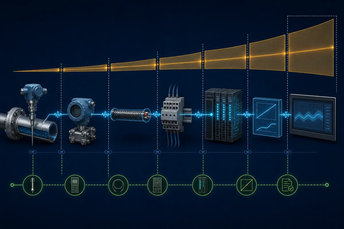
A numeric temperature without quality and age is unsafe to consume. Use explicit states such as Good, Suspect, Bad and Stale, or map the device's documented quality model into an equivalent contract. Detect raw underrange/overrange, channel fault, open sensor, communication loss, impossible rate and stale update separately where evidence supports them.
When quality becomes bad, ordinary heat control should not treat the last good value as live. Freeze-for-display may be useful if visibly marked stale, but control needs the approved fallback: inhibit heat, move to a defined manual value, transfer to a redundant validated measurement, or execute another hazard-reviewed response. Delay and recovery filters can stop chatter, but must not hide dangerous measurement loss.
| Quality state | Meaning | Control treatment | Operator evidence |
|---|---|---|---|
| Good | source status, range and age pass | eligible for ordinary control | live value and normal quality |
| Suspect | value remains usable only under an approved degraded rule | apply explicit limitation or supervision | reason, start time and active limitation |
| Bad | source diagnostic or plausibility check fails | apply approved fallback; do not treat PV as healthy | first cause, raw/status values and alarm |
| Stale | value has not updated within its contract | apply approved stale-data fallback | last update, age and communication state |
Select the right control strategy
On/off with hysteresis
On/off control suits applications where cycling and temperature variation are acceptable. With SP = 60 °C and half-band 2 °C, heat turns on below 58 °C and off above 62 °C. Between those points it retains the previous request. That stateful deadband prevents rapid switching near setpoint.
IF NOT TempQualityGood OR HighLimitActive OR NOT AutoEnable THEN
    HeatRequest := FALSE;
ELSIF Temperature_C <= (Setpoint_C - HalfBand_C) THEN
    HeatRequest := TRUE;
ELSIF Temperature_C >= (Setpoint_C + HalfBand_C) THEN
    HeatRequest := FALSE;
END_IF;
This is generic IEC-style Structured Text, not drop-in vendor code. Test comparisons, initial state, scan order and invalid-value behavior. A minimum on/off time may be needed for compressors, contactors or burners, but it changes response and must follow equipment requirements.
Staged and time-proportioned control
Multiple heaters, compressors or fans can be staged by error or controller demand. Use different pickup and dropout thresholds, minimum run/off timers, proven availability and lead/lag rotation. Do not command every stage from one threshold. If Stage 1 fails to prove, retain that first-out cause and follow the approved degraded strategy rather than silently masking it with every remaining stage.
A resistive heater switched by a suitable solid-state device may use a fixed window. A 30% demand in a 10-second window requests three seconds on and seven off. The window must suit the final element; rapidly cycling a mechanical contactor is not equivalent to a correctly designed solid-state stage. Compare requested duty with current or auxiliary feedback.
PID control
PID is justified when proportional modulation improves regulation and the process is sufficiently repeatable. Execute the instruction at the interval assumed by its configuration. Confirm dependent or independent gains, seconds or minutes, derivative on error or PV, internal or external timing, and documented anti-windup/tracking. Identical-looking gains can behave differently across forms.
| Strategy | Good fit | Main evidence | Frequent mistake |
|---|---|---|---|
| on/off with hysteresis | acceptable band, simple element | cycle rate and transitions | stateless comparison that chatters |
| staged | discrete capacity steps | stage proof, rotation and timers | identical thresholds for every stage |
| time proportioning | slow load, suitable switchgear | fixed window and applied duty | cycling an unsuitable contactor |
| PID | modulating element, tighter regulation | timing, modes, limits and trends | tuning before proving hardware |
| cascade | measurable fast secondary variable | inner loop significantly faster | tuning both loops together |
| feedforward plus feedback | repeatable measured disturbance | model and separate contribution | replacing feedback with a model |
PLC program architecture for a heater loop
Use fixed execution order and explicit modes
A maintainable program separates acquisition, validation, scaling, mode/setpoint management, controller calculation, limit/interlock arbitration, final-element command, feedback proof, alarm state and history. That order stops a controller consuming old quality or an alarm reading last scan's command without anyone knowing.
For PID, schedule the calculation in a periodic task or use the instruction's documented timing mode. UI and communications should not determine the interval. Trend or watchdog actual execution when the platform permits. A controller configured for one second does not have the same integral and derivative behavior if called unpredictably.
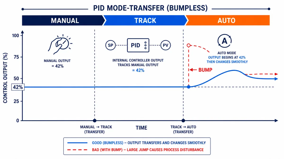
At minimum, distinguish Off, Manual and Auto. Some projects need Track, Hold, Cascade or Maintenance, but names alone do not define behavior. Specify the source of SP/output, whether PID continues calculating, how tracking works, what happens to integral state and what value is used on transfer. Manual-to-auto should not create a large bump; use the exact instruction's documented tracking or initialization method. Stopping the call can freeze state or violate timing assumptions.
| Mode | Output source | PID state expectation | Exit condition to prove |
|---|---|---|---|
| Off | defined safe ordinary-control request | documented reset, track or retained behavior | no residual applied heat |
| Manual | authorized bounded manual request | tracks applied output using supported mechanism | aligned and deliberately misaligned transfer |
| Auto | PID or selected automatic strategy | executes at configured interval | limits, bad PV and interlock transitions |
| Cascade | outer-loop remote setpoint | both loops expose mode and saturation | inner manual/bad-quality fallback |
(* Generic teaching structure: adapt under an approved project process. *)
TempValid := AI_ChannelGood
             AND (RawTemp >= RawFaultLow)
             AND (RawTemp <= RawFaultHigh)
             AND NOT TempStale;

IF TempValid THEN
    Temperature_C := (REAL(RawTemp - RawAt4mA) * 300.0)
                     / REAL(RawAt20mA - RawAt4mA);
END_IF;

HeatPermissive := AutoEnable AND TempValid AND FanProven
                  AND NOT HighLimitActive AND NOT SafetyTrip;

(* PID_Request is calculated in the configured periodic task. *)
HeatRequest_pct := LIMIT(0.0, PID_Request_pct, MaxHeat_pct);

IF HeatPermissive THEN
    HeatApplied_pct := HeatRequest_pct;
ELSE
    HeatApplied_pct := 0.0;
END_IF;

HeaterCommand := HeatApplied_pct > 0.1;
ProofTimer(IN := HeaterCommand AND NOT HeaterFeedback, PT := T#2s);
IF ProofTimer.Q AND NOT HeatProofFault THEN
    HeatProofFault := TRUE; (* first-out; controlled reset elsewhere *)
END_IF;
The snippet intentionally omits a vendor PID call and safety implementation. Those depend on CPU, module, instruction, electrical design and process. It shows portable boundaries: quality before control, request before permission, applied output after arbitration and feedback proof after command.
PID limits, saturation and thermal response
Suppose PID calculates 112%, the project limit is 80%, and power management permits 55%. Record all three: raw 112%, controller-limited request 80%, applied demand 55%. Retaining only 55% hides saturation; retaining only 112% pretends the process received energy that never arrived.
Integral windup occurs when integral action keeps demanding correction that cannot be applied. Use the instruction's supported anti-windup and external-reset or tracking mechanism. A clamp after PID can protect an output value while leaving integral state wound up, so it is not automatically anti-windup.
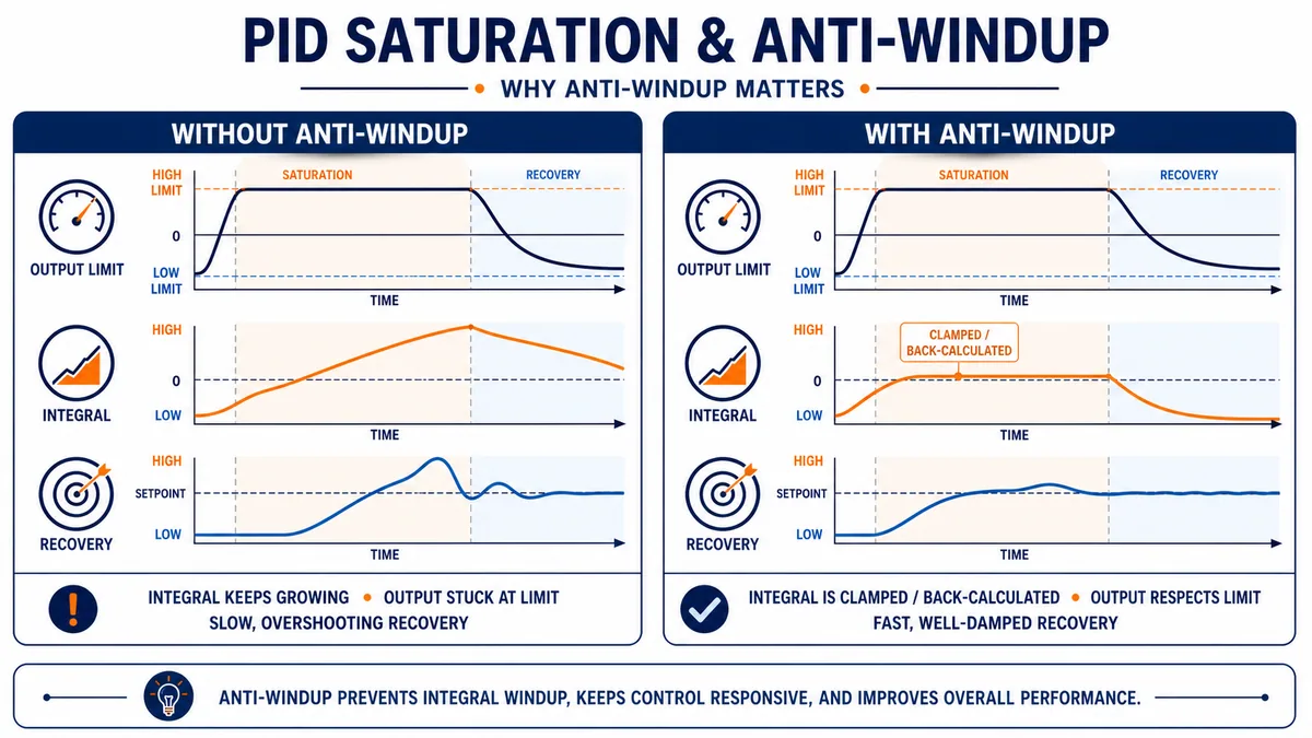
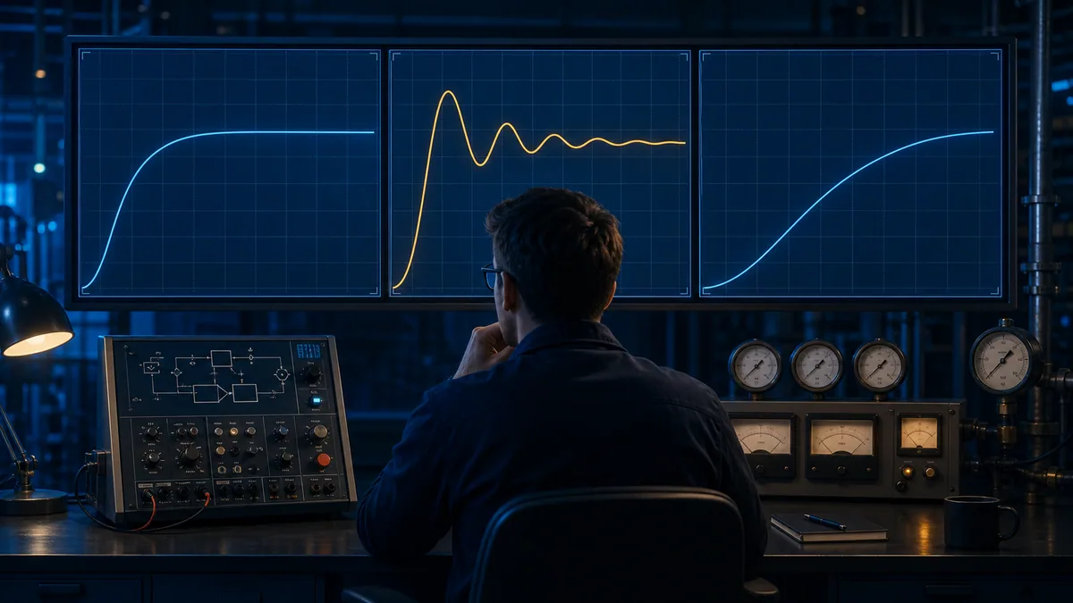
Temperature processes often respond slowly and keep moving after heat is removed because energy remains in elements, walls, product or fluid. Sensor location adds delay. Aggressive tuning cannot remove physical dead time; it can amplify oscillation. Trend setpoint, PV, output, mode, quality, limits and disturbances through enough cycles to see the dominant time scale.
Overshoot with output already at zero can indicate stored heat, sensor lag or excessive integral history. Slow rise while output is saturated may indicate insufficient heater capacity, high loss, an open stage or wrong scale—not timid gains. Oscillation with sawtooth applied output may originate in a valve, staged threshold or proportioning window instead of PID arithmetic.
Cascade and feedforward
Cascade uses an outer temperature loop to set the target of a faster inner loop such as steam flow, jacket temperature or heater current. Prove and tune the inner loop first. It should be meaningfully faster and expose its own mode, quality, limits and applied output. Cascade cannot compensate for an unreliable inner measurement.
Feedforward adds predicted demand from a measurable disturbance such as throughput, inlet temperature or airflow. Feedback still corrects model error. Record the feedforward contribution separately, bound the total and test loss or corruption of the disturbance signal. A relationship learned in one region is not automatically valid across recipes, equipment states or seasons.
| Advanced function | Minimum contract | Failure fallback |
|---|---|---|
| temperature-to-flow cascade | inner PV/SP/output, quality, mode, limits, rate | approved tracking/manual behavior |
| ambient feedforward | disturbance, units, model, delay, valid range | visibly remove feedforward |
| split-range heat/cool | sequencing and both applied outputs | approved neutral/single-side action |
| gain scheduling | region definition and bumpless transition | documented base parameter set |
Commissioning sequence and acceptance tests
Begin with documents and a de-energized inspection under the site's safe-work procedure. Verify sensor type/range/wiring, module configuration, output hardware, protection, actuator capacity, fail state and software manifest. Prove the measurement chain at multiple points with an appropriate reference. Only after signal quality and action direction are correct should authorized personnel exercise manual output and confirm physical feedback.
Start closed-loop work with conservative approved limits and synchronized trending. Establish a repeatable baseline, change one parameter or disturbance at a time, and retain before/after evidence. Confirm modes, constraints, faults and restart states—not only a successful setpoint step.
| Test | Stimulus | Expected evidence |
|---|---|---|
| lower/mid/upper reference | three known inputs | raw, scaled value, error, quality |
| sensor open/bad | approved simulation or source | bad quality, alarm, heat fallback |
| stale value | stop/age test update | stale state; last value not healthy |
| action direction | small authorized demand | feedback and PV move as expected |
| command without feedback | suppress test proof | timeout and first-out cause |
| manual-to-auto | aligned then misaligned | documented bounded transition |
| output limit | request above maximum | raw/requested/applied remain distinct |
| setpoint step | bounded repeatable change | response and acceptance measures |
| load disturbance | repeatable approved disturbance | deviation, recovery, effort |
| restart | controlled power/restart | defined mode, output and retention |
| high limit | separately approved proof | heat removed, evidence retained |
| restoration | clear cause, controlled reset | no unapproved automatic restart |
Troubleshooting PLC temperature control
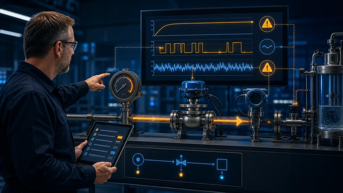
Start with symptom time and retained evidence. Check reference and process condition, then sensor, wiring/transmitter, raw module value/status, scaling, quality, controller inputs, requested output, constraints, applied output, feedback and physical response. Changing gains before this chain is proved makes evidence harder to interpret.
| Symptom | First evidence | Likely boundary | Avoid |
|---|---|---|---|
| PV fixed | field reference vs raw and timestamp | sensor, input or stale link | tuning PID |
| PV reads backward | applied temperature vs polarity/type | thermocouple configuration | negating in logic |
| heater requested, no warming | request, command, current and heat path | interlock, element or capacity | more integral gain |
| 100% output, slow rise | applied power, loss, load, scaling | capacity or measurement | assuming low gain |
| overshoot after output zero | integral, stored heat, sensor lag | windup/dynamics | arbitrary delay |
| regular cycling | output, stage/window and PV | hysteresis or element | blaming noise alone |
| auto transfer bump | manual/applied/tracked values | mode tracking | stopping PID calls |
| random spikes | raw, status, wiring and event time | measurement/EMC | heavy filtering first |
| HMI-only error | PLC value vs display conversion | units/tag mapping | sensor calibration |
| heat stays on after fault | permissive, command, feedback | ownership/welded element | reset before isolation |
Safety, cybersecurity and change control
Temperature hazards can include fire, pressure, decomposition, burns, product damage, freezing and hazardous release. Ordinary PLC control is not automatically a safety function. Independent limits, shutdown devices, relief, ventilation, combustion safeguards or safety-rated systems may be required by hazard analysis and applicable codes. A software alarm is not a substitute for required protection.
Authorized personnel must follow hazardous-energy and electrical safe-work procedures. Do not force outputs, bypass interlocks or tune a live hazardous process merely because an editor allows it. Use management of change for sensor range, units, PID form, gains, limits, timing, mode behavior, alarms and output ownership. Retain the approved project, versions, configuration, tests and as-left values.
Treat remote access, engineering workstations and controller changes as OT security matters. NIST SP 800-82 Rev. 3 recommends controls appropriate to OT constraints. Backups, least privilege, controlled pathways, logging and tested recovery protect integrity and availability; they do not remove process-safety obligations.
Frequently asked questions
What is PLC temperature control?
It validates and scales temperature, compares it with a target and controls heating or cooling through on/off, staged, time-proportioned or modulating logic. A complete design also manages quality, modes, limits, feedback, alarms and independent protection.
How do I program temperature control in a PLC?
Define the process and safety contract, prove the sensor, scale to units, create quality states, choose a strategy, separate request from permissive/command/feedback, add mode and limit handling, then execute staged tests. Translate the generic pattern into documented platform instructions.
Should I use on/off or PID temperature control?
Use on/off when the permitted band and cycling allow it. Consider PID when a suitable modulating element and repeatable process justify tighter control. Sensor quality, delay, actuator authority and independent limits matter more than the label.
What hysteresis should heater control use?
There is no universal value. Balance permitted variation, sensor noise, process lag and final-element cycle limits. Record pickup/dropout thresholds and test both directions under representative load.
How is a 4–20 mA temperature signal scaled?
Map configured raw 4 mA and 20 mA values to the transmitter's engineering endpoints with a linear equation. Keep raw under/overrange for quality logic; do not clamp away diagnostic evidence.
Is an RTD better than a thermocouple?
Neither is universal. RTDs often suit accurate moderate ranges; thermocouples cover wider and higher ranges with different wiring and compensation concerns. Select from range, accuracy, response, environment and module compatibility.
What should happen if the sensor fails?
Mark the measurement bad or stale, alarm it and apply the hazard-reviewed fallback—often inhibiting ordinary heat. Do not retain a last value while labeling it healthy. Independent protection remains separate.
Why does my temperature loop overshoot?
Possible causes include integral history, aggressive gains, stored heat, sensor lag, dead time, oversized equipment, slow tasks or transfer mismatch. Compare PV with raw, limited and applied output before changing gains.
Why is heater output 100% but temperature rises slowly?
Check whether 100% is requested or applied, then verify scaling, heater current/feedback, stages, load, heat loss and capacity. Tuning cannot create missing power.
Can PID run in a normal cyclic task?
Only if documented timing requirements are met and the interval is controlled. A periodic task or supported timing mode is easier to prove. Record actual interval and translate gain units correctly.
Should PID stop when the heater is interlocked?
Not by assumption. Skipping calls may freeze state or violate timing. Use documented manual, tracking, hold or anti-windup behavior while arbitration enforces the interlock.
How do I make manual-to-auto transfer bumpless?
Align internal state or tracking input with applied manual output using the documented mechanism, then test aligned and deliberately misaligned transfers. Copying one value may not initialize every state.
Can a simulator tune a real oven?
A simulator can teach cause and effect and exercise faults. It cannot validate actual sensor lag, capacity, nonlinearities, hazards or vendor instruction behavior unless a qualified workflow validates the model. Repeat approved tests on the exact system.
What should be trended during commissioning?
Trend synchronized SP, PV, quality/age, mode, raw PID output, requested/applied output, limits, command, feedback, alarms, task interval and disturbances. Record configuration and revision with the trace.
Sources, review scope and limitations
This independent guide was reviewed on August 31, 2026. Verify current editions and exact installed hardware, firmware and software.
- IEC 60751 industrial platinum resistance thermometers — IEC
- IEC 60584-1 thermocouple specifications and tolerances — IEC
- NIST ITS-90 thermocouple database
- IEC 61131-3:2025 programming languages — IEC
- ISA-TR5.9-2023 overview of PID forms and units — ISA
- PID equation optimization — ISA
- S7-1200/S7-1500 PID control manual, November 2025 — Siemens
- Logix PID configuration and equations — Rockwell Automation
- Anti-reset windup and bumpless transfer — Rockwell Automation
- Timing modes — Rockwell Automation
- PlantPAx PPID — Rockwell Automation
- PID function block — Schneider Electric
- FB_PID function block — Schneider Electric
- Control-system fundamentals: PID — National Instruments
- PID Tuner controller forms — MathWorks
- Anti-windup control — MathWorks
- NIST SP 800-82 Rev. 3 OT security guide
- 29 CFR 1910.147 hazardous energy — OSHA
- OSHA electrical safety
- OSHA safety and health programs
The equations, generic Structured Text, calculations, tables, downloads and reused in-house original illustrations are teaching artifacts—not vendor code, a validated model, drawing, P&ID, instrument specification, tuning prescription, safety architecture, calibration certificate or field authorization.
This page does not authorize connecting, energizing, operating, forcing, bypassing, tuning or testing installed equipment. Qualified personnel must apply the site hazard assessment, hazardous-energy and electrical procedures, validated limits, manufacturer instructions, independent protection, management of change, cybersecurity and approved commissioning/recovery procedures.


